
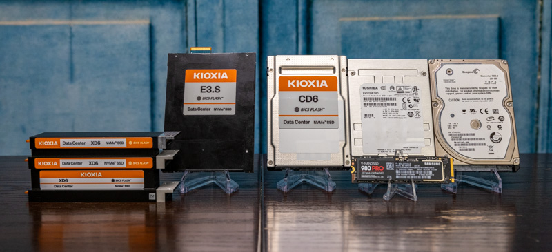
In the not too distant future (2022) we are going to see a rapid transition away from two beloved SSD form factors in servers. Both the M.2 and 2.5″ SSD form factors have been around for many years. As we transition into the PCIe Gen5 SSD era, EDSFF is going to be what many of STH’s community will want. Instead of M.2 and 2.5″ we are going to have E1.S, E1.L, E3.S, and E3.L along with a mm designation that means something different than it does with M.2 SSDs. If that sounds confusing, you are in luck. At STH, we managed to grab some drives (thanks to Kioxia for the help here) to be able to show you exactly how the world of storage and some PCIe memory/ accelerators will work.
Video Version
As part of our recent series discussing the next generation of servers, we have a video on this as well:
We always suggest opening the video in a YouTube tab or window for a better viewing experience.
The Ultra-important Background
The 2.5″ form factors that we see today have been around for many years since PrairieTek introduced the form factor in 1988. Over the subsequent 20-21 years (see what we did there) it became a popular form factor for hard drives that would go in notebooks and even servers. Indeed the fourth article on STH was looking at an issue with an Adaptec RAID controller and Seagate Savvio 15K rpm 2.5″ drives. In servers, the 2.5″ form factor made 15K rpm spindle speeds more attainable due to the smaller media diameter. It also meant that one could fit more drives in a chassis increasing IOPS and throughput. For example, a 2U server generally can fit 12x 3.5″ drive bays in front or 24x 2.5″ drive bays. In the era of hard drives where devices were not as fast as interfaces, doubling density may have decreased capacity, but there were plenty of applications willing to trade capacity for doubling the performance.
When SSDs came about in SATA and SAS interfaces, 2.5″ was the logical choice because they fit into dense chassis and one could interchangeably use hard drives or SSDs. One drive bay allowed either type of media which was important when the 10K and 15K rpm server drives still had some value versus SSDs.
M.2 was started primarily for notebooks because 2.5″ SSDs were impractically large. SSDs have the advantage of not having to fit spinning media, motors, heads, actuators, and other components. Instead, they need a few chips, a PCB, and a connector. Eventually, server manufacturers saw the volume being driven on M.2 with notebooks and adopted M.2, especially for boot media.
NVMe hit the market and although there were generations of PCIe add-in-cards, drive vendors used 2.5″ and M.2 form factors to make NVMe SSDs. The existing infrastructure was already there.
There are some big challenges today with these form factors. M.2, for example, has run into cooling challenges, especially with PCIe Gen4 SSDs. It is now common to see a small SSD with a large heatsink. M.2 NVMe SSDs are also not hot-swappable because the connector was not made for hot-swapping.
2.5″ SSDs at PCIe Gen4 are also using more power and thus generate more heat. The 2.5″ form factor was not designed for 70W SSDs for example. Also, we mentioned earlier having a ~24 bay limit using standard 15mm 2.5″ SSDs in a 2U chassis so density is somewhat limited. Overall, this is simply one of those cases where using a 2.5″ form factor designed to fit a spinning disk no longer makes sense.
While we are starting to see challenges at PCIe Gen4, with PCIe Gen5, those problems become more acute. In next-generation servers, we will have more PCIe lanes (128x lanes in a next-gen dual-socket server will be considered lower-end.) As such, the potential to have more PCIe lanes means we can have denser configurations which means the potential to use more SSDs and accelerators.
That is why we need a new standard, so let us get into the E1 and E3 ESFF standards to see what we will transition to.
EDSFF Overview
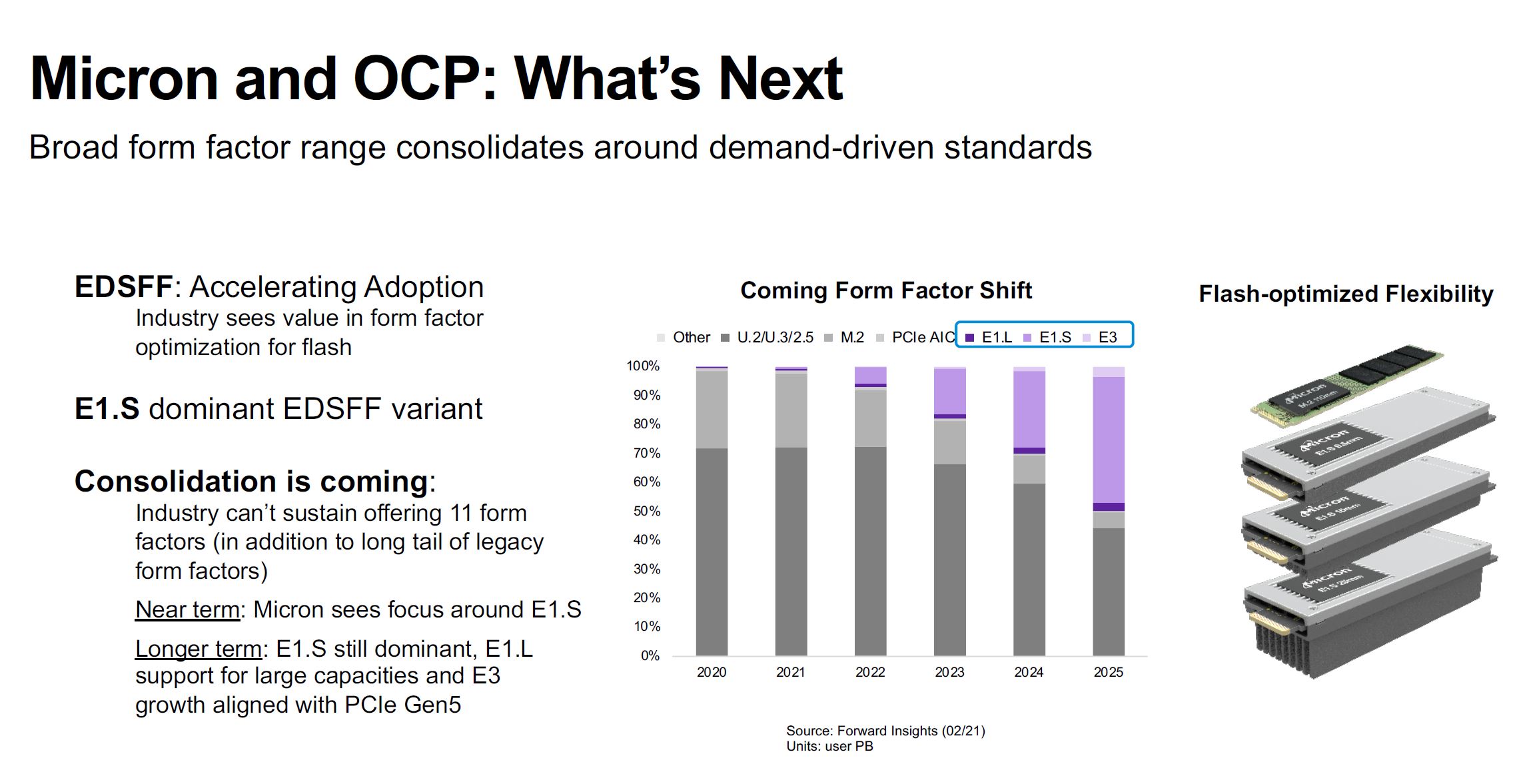
EDSFF is the next-generation set of form factors that are set to re-define servers. The two main varieties will be the 1U sized E1 and the 2U sized E3 form factors. The market is expected to shift quickly to EDSFF with projections putting around half of the capacity will be on EDSFF by 2025. While U.2 and M.2 are popular today, the new E1.S form factors specifically are being seen as the big drivers of this transition.
Let us get into both the E1 and E3 form factors to see what the big deal is and why we are about to see this transition accelerate.
EDSFF E1 Form Factors
The two big form factor families for E1 are E1.L and E1.S. In this case, L stands for “Long” and S stands for “Short”. The E1.S will be more popular, but the E1.L was a driving force in the early days so we will focus on that first.
EDSFF E1.L Form Factor
The E1.L form factor is often called the “ruler” SSD form factor. The original idea was that a longer 1U drive could fit more NAND packages and provide more surface area for cooling thereby enabling larger drives.
We previously took a look at the E1.L form factor about a year ago in our Hands-on with the 1U Half-Petabyte Supermicro EDSFF Server article. Here is the video for that:
With 32TB class drives that came out in the last year, this is now a ~1PB/U storage solution.
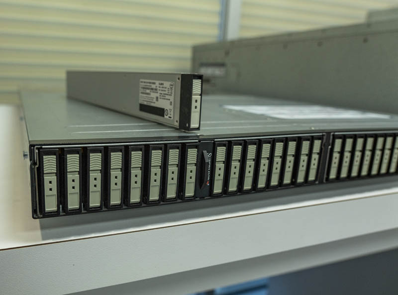
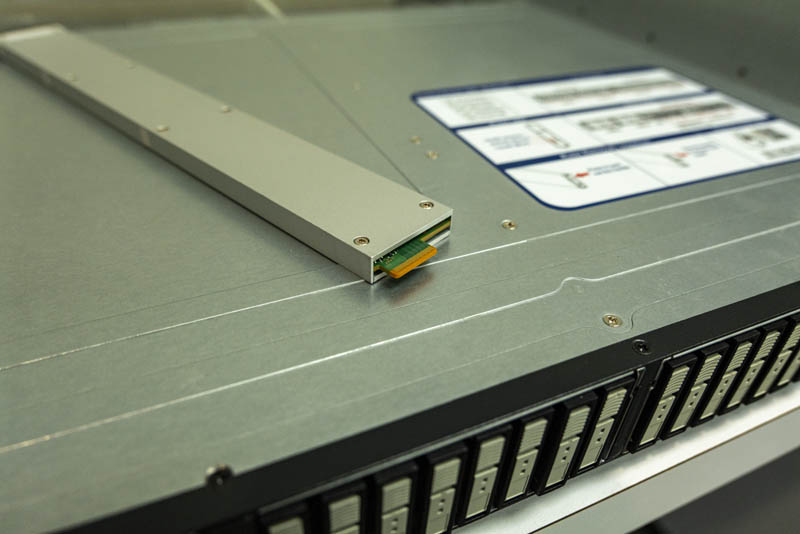
The challenge with EDSFF E1.L is that it is so long. For many servers, having a long SSD like this (318.75mm or ~12.5in) is substantial. We often see servers in the 30-36in range so a SSD this long would take up a third or more of the depth of servers that fit in standard racks.
EDSFF E1.L has two widths either 9.5mm or 18mm that allows for up to 25W or 40W respectively. That is actually a big deal since even 32 drives in the front of a system using 25W each is 800W of power consumption there. We have been discussing next-gen server power consumption as part of this series, but this is a clear example of where that will
EDSFF E1.S Form Factor
The real star of the EDSFF transition is set to be E1.S. E1.S trades length for width.
There are a total of five width options that share the same PCB. The 5.9mm device is more akin to what we see for a standard M.2 drive with no real cooler on the device. The 8.01mm heat spreader is not large enough to provide enough cooling for PCIe Gen5 SSDs. As such, the main three we will see are the 9.5mm, 15mm, and 25mm E1.S SSDs.

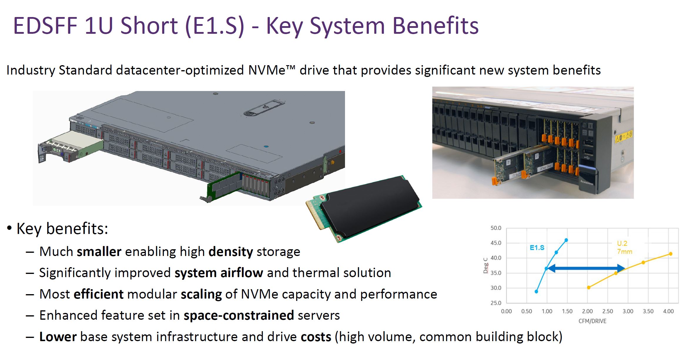
In the case of the E1.S 9.5mm form factor, we get a drive that is relatively thin and thus one can densely pack SSDs into a given chassis.
Since the E1.S drives are designed to stand vertically in a 1U chassis, and they are thinner than existing U.2/ U.3/ 2.5″ drives, more drives can be connected to a server. Here is Intel’s E1.S mechanical fit study for the drives.
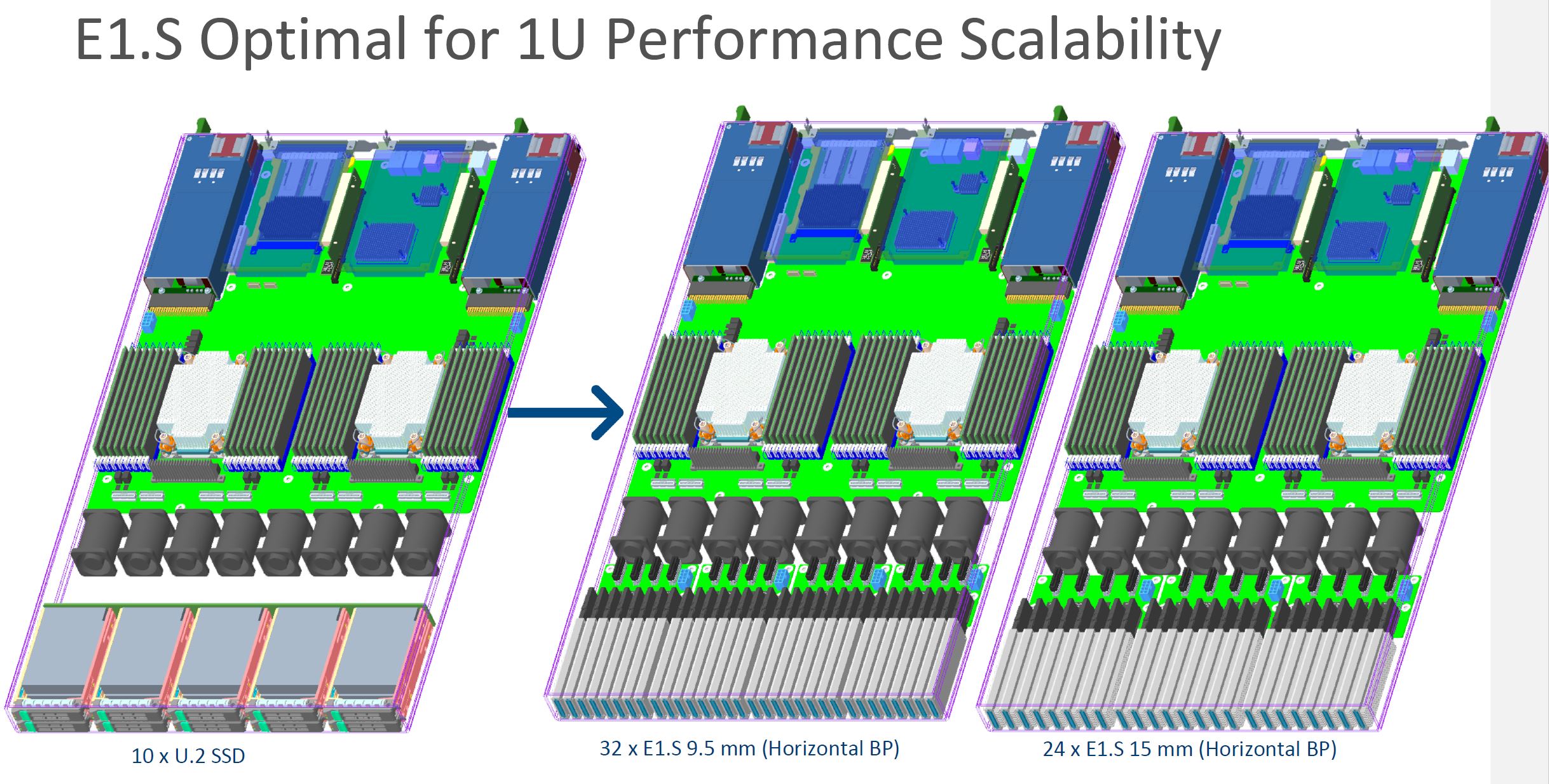
Here we can see the 9.5mm drives at 32 across in a 1U system while still providing airflow to the CPU sockets. That is just over a 3x density improvement over a U.2 / U.3 SSD solution using 15mm 2.5″ drives.
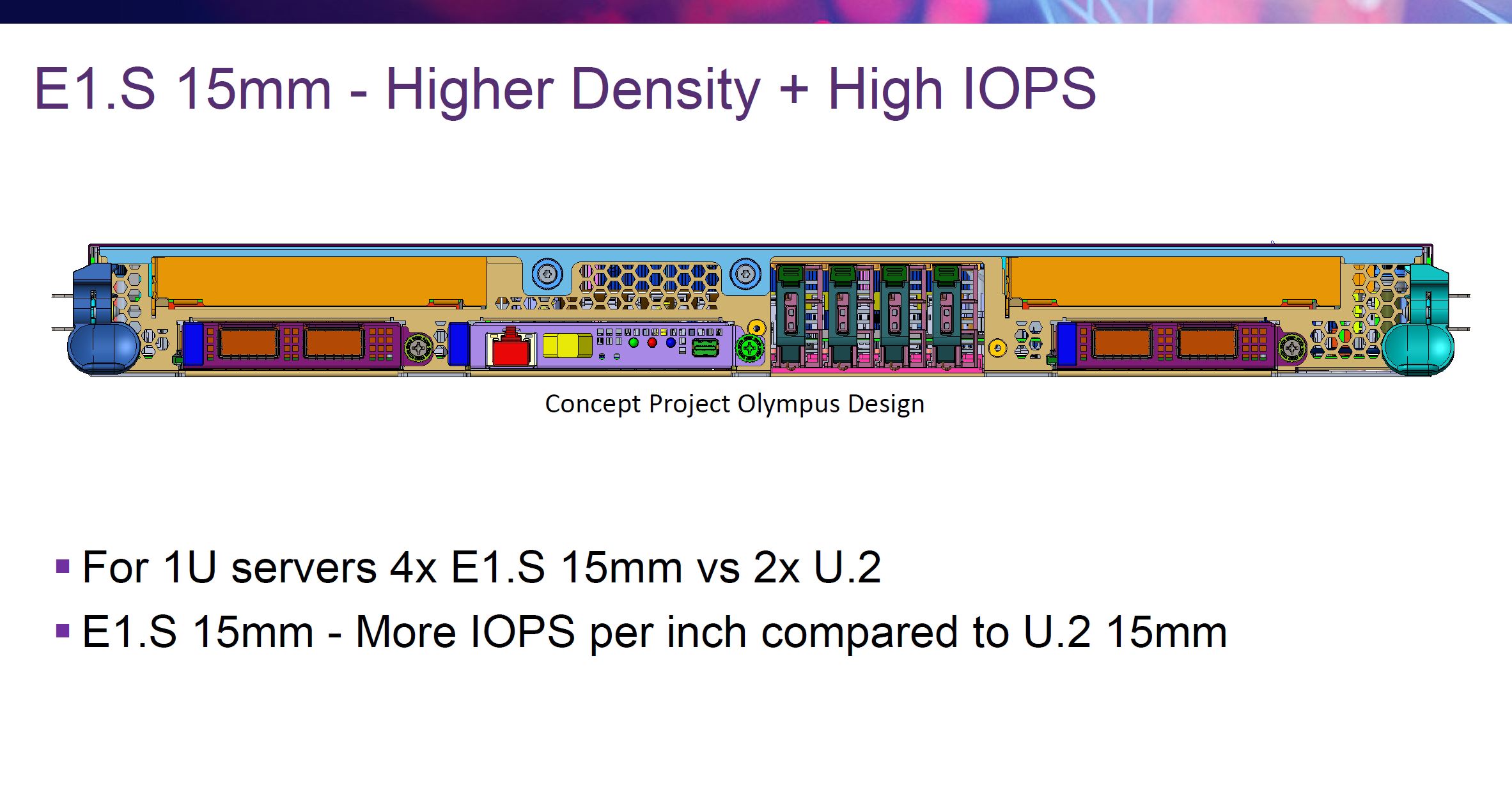
The other form factor shown above is the E1.S 15mm which is the same thickness as our traditional 2.5″ SSDs. On the above mechanical study, we see 24x E1.S 15mm drives in a 1U server. This may not seem like a big deal, but today we usually see 24x 2.5″ SSD chassis which doubles the SSD density at a rack level.
These E1.S 15mm drives use that extra space for cooling. This extra space allows for 25W devices. Power will become a major challenge in the next generation of PCIe Gen5 SSDs because the interface performance is so high that moving data around at those speeds uses a lot of power.
The big drive, however, is the E1.S 25mm form factor. This allows for 25W+ drives by adding an additional 10mm for cooling.
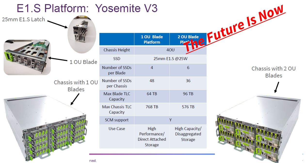
For some context here, we recently covered that Facebook Leveraging EDSFF E1.S 25mm in Yosemite V3. A big part of that is that the 25mm drives allowed Facebook to have the right mix of performance, power, and airflow for its data center.
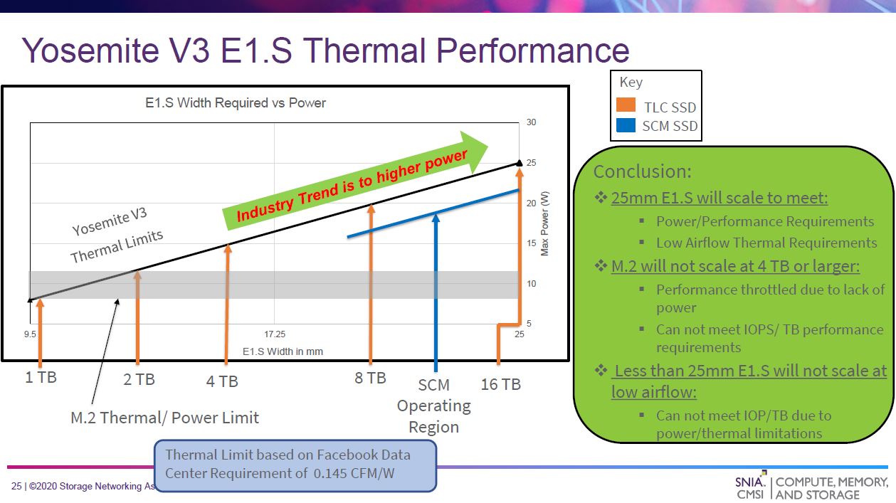
Facebook is using E1.S SSDs in its Yosemite V3 Open Compute Project platform.
While some may immediately focus on the density loss of moving from 9.5mm to 25mm, that is only part of the story. With 20-25W drives, power and thermals for the server will be come to a challenge. For many applications, using 25mm drives that do not need as much airflow will be a better fit.
An example of how EDSFF can be used in the Microsoft Project Olympus design that uses 15mm E1.S drives to provide four NVMe SSDs in a compact footprint while still allowing for multiple front panel PCIe / OCP NIC slots. The form factor change allows for storage density not just to fit the maximum number of drives on an I/O plate. It also frees up panel space for other functions.
Although we have focused on Facebook and Microsoft, traditional vendors will support E1.S as well. Here is an example of a Lenovo design mixing 2.5″ and E1.S SSDs. One can see how much denser the E1.S sections are.
Overall, E1.S by combining a smaller form factor that fits in a 1U (more like a M.2 drive in some ways) we get more flexibility in how servers can be designed as well as options to drive higher levels of performance.
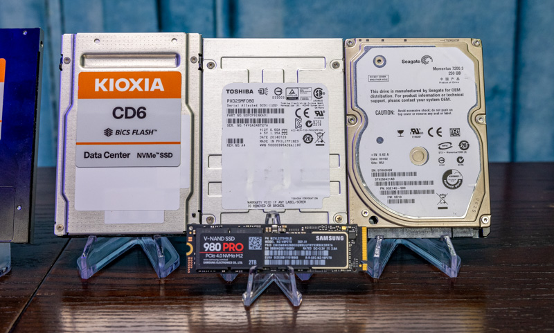
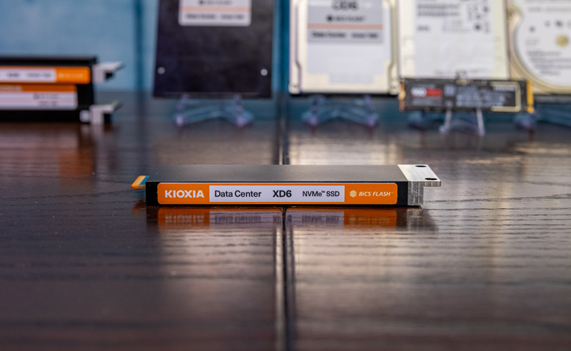
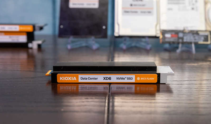
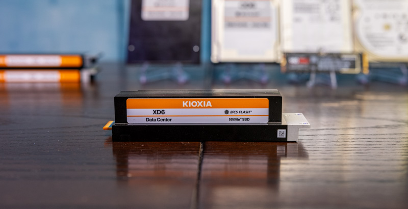
As a quick aside, on the E1.S versus M.2 storage, here is an example showing a M.2 drive compared to a E1.S 9.5mm drive:
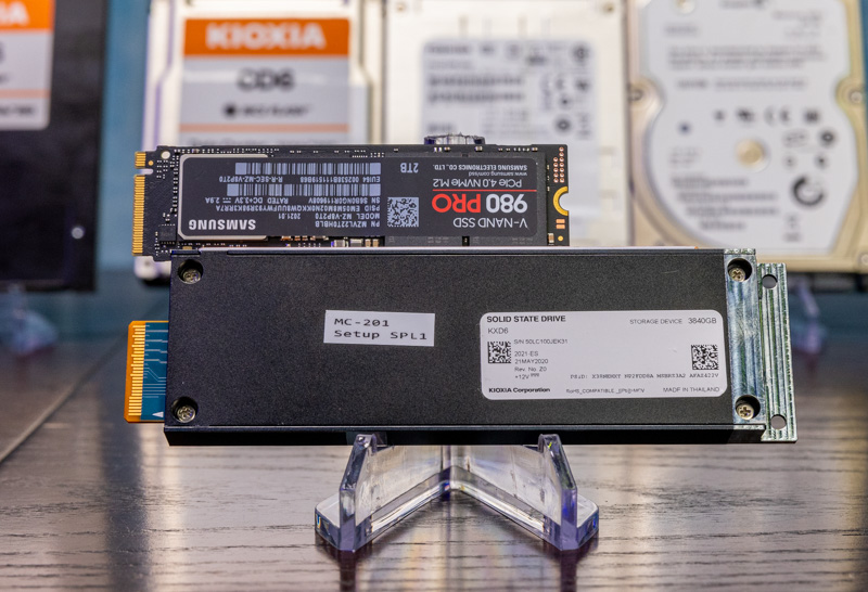
The E1.S drives one can see are encased in more substantial cooling and have features that are required for servers such as the ability to hot-plug/ hot-swap drives and even the aligning/ retention mechanisms. More on latches later.
The key takeaway though is that the E1.S form factor is going to be the key industry driver towards an EDSFF form factor transition.
Still, there is a form factor we can think of as closer to a relative of the 2.5″ form factor, and that is E3.


This is otherwise known as “ruler” storage due to its dimensions. I have spoken to several OEM’s about ruler storage and its viability in the future. The problem is standards. When ruler storage was proposed, everyone was excited about it, but no one wanted to agree on format and connectors even though Intel had one in place. HPE, Dell, Supermicro, Lenovo all had their ideas on how ruler storage should operate. Most datacenter folks saw this as no different than the disk caddy differences. No OEM wanted to lose margin and certifications by having ruler storage be 100% interoperable between server brands. As long as the OEM’s maintain the same standards and don’t stick some proprietary front end snap in that only works on their equipment, it should take off pretty fast. If they wander off, then look for ridiculous unit pricing to maintain their margins.
I was excited about EDSFF when I found out about them a year or so ago, with claims about being “optimized” for NVMe form factors and doing denser configs with 30TB drives. Unfortunately that never happened, and the OEMs and ODMs stuck to U.2/U.3 outside of niche chassis SKUs. Now we have 30TB U.3 NVMe drives coming out and EDSFF never took off.
I hope the adoption curve changes and EDSFF differentiates itself, but we will see if this ever makes it out of niche use cases.
U.3 is dead tech funded by Broadcom to make it’s SAS controllers still relevant It makes me sick to see all the tech sites repping U.3
Very informative, thank you. FYI, there’s an unfinished sentence: “We have been discussing next-gen server power consumption as part of this series, but this is a clear example of where that will…”
Is there any mention of a servers bay can still use a SAS connection and ED3 at the same time, so OEMs can use both SATA/SAS and E3 drives interchangeably in bays?
So what is the plan for storage solutions for embedded network appliances? There are a lot of requirements for boot drives, and non-user access storage applications like the M.2 NGFF form factor. From what I am hearing, Micron, and Intel are planning on abandoning M.2 NGFF form factors starting with GEN5 PCIe. Are there plans for an EDSFF embedded form factor?
3 years later and I still see a lack of adapters/cables for plugging EDSFF drivers into servers with no pre-installed EDSFF interfaces. Maybe a PCI card where cables to RDSFF drives and/or EDSFF backplanes could connect to the PCIe bus, perhaps with an on-card PCIe bridge chip to decouple PCIe slots from ESD and signal strength issues at the drive connector. Also to use a single x16 slot to handle over 4 EDSFF drives without custom drivers, just the generic PCIe bridge support in the server OS.
Without such adapter products, EDSFF use will be limited to server motherboards designed from the ground up to only work with those drives.
JD – Just as a heads-up – In the PCIe Gen6 generation, the U.2 connector is going away for storage. So adoption of EDSFF will no longer be an issue
Comments are closed.