
The purpose of this article is to take what we did in our Building a Lab Part 1 article and to begin to put our plans into action. We will be building out our network, and preparing it for our new lab. Once completed, we will be ready to move on and learn a little more about our storage server before completing the lab configuration.
Before we start, it is important to understand the OSI Model for networking. When we discuss terms like “Layer 1” or “Layer 2” or “Layer 3” we are referring to the concepts as defined in the OSI model.
Preface on our Router Configuration
Before we begin configuring our new lab, we need to first prepare our existing network for the addition. You do not have to get as fancy as we did, especially if you are just starting out. Most of what we are doing here could be accomplished with a wireless router hacked with DD-WRT. DD-WRT is VLAN aware, and so would fit the job nicely. A VLAN is a virtual lan, or a way of creating isolated networks without having to physically run separate hardware.
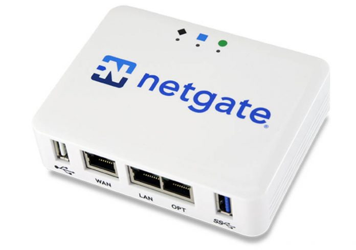
Another option could be pfSense in something like the SG-1100 (see more here). In that case, you would use one interface for your internal network (using the LAN port) and one for your lab (using the OPT port).
For the sake of the article, we are assuming you are using a managed switch or a VLAN aware firewall/router.
If you are using your ISP provided gateway and you cannot create VLANS, you will need to make one alteration. Anything in the Mikrotik configuration section which is labeled with VLAN 99 should be substituted with VLAN 1 and you then will be able to follow along unfettered.
Networking Setup – Configuring the Core
In our case, our router is located in our MDF, or main distribution frame. We are using an HP E3800 as a core/distribution switch. A core switch is one that is the primary entity responsible for providing services to a network. A distribution switch is one which connects other switches back to the rest of the network. This is setup as a layer 3 switch. What that means is this switch is also acting as a router. In our case, it does all of our inter-VLAN routing. This switch is in a stacked configuration, which means there is actually more than one physical switch (in our case it is two). You build switches in this configuration for redundancy in case of failure and ease of management.
To accompany the HP stack, we are using pfSense as our firewall. In our environment, its primary role is to protect the edge, or where our network connects to the internet. It has some important security features enabled, most important being Suricata. Intrusion Detection and Prevention (IDS/IPS) systems like Suricata are similar to antivirus software, but for network packets. Traditional antivirus uses “definitions” to determine whether a file is malware. Similarly, Suricata examines packets as they come in and go out of your network, and if they meet certain criteria it will either alert you or (depending on how it is configured) block the traffic altogether.
As such, the following steps are what we did and they may not apply to your existing environment. However, there are important considerations that need to be made, so we felt it necessary to share our process to help you understand how we are doing layer 3 (network layer/routing) and what security measures we already have in place.
Configuring our HP Switch
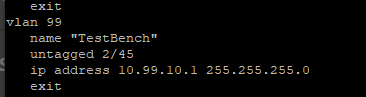
On our core switch, we have created a new VLAN called TestBench with a VLAN ID of 99. We then identified the port on our switch where the MikroTik CRS305-1G-4S+IN was plugged into and then untagged it on that VLAN. Untagging (or an access port in Cisco speak) is how you tell the switch to put traffic from a device on a specific network. The device (in this case our CRS305) is unaware of any VLAN configuration.
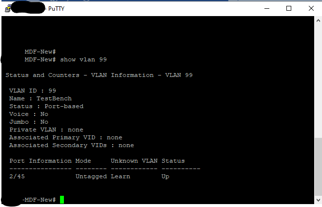
Conversely, if we tagged VLAN 99 on the port on the HP switch, we would then need to tell the CRS305. We would have also had to tag VLAN 99 on the port on the CRS305 that goes to the HP switch. What switches are doing is they are modifying the frames which are sent (at layer 2) to include this information. This gives you the ability to take multiple networks and send them over a single cable or LAG (link aggregation). We do not plan on carrying any other VLANs to our lab, so we are just untagging.
Since IP Routing is enabled on the HP Core, and we want our datacenter to be able to get out to the outside world, we need to give this VLAN an IP Address. Doing this action is what allows the HP switch to route traffic between the various internal networks and our firewall. For the purpose of this lab we are going to assign a new private class C subnet (256 addresses) and give VLAN 99 an address of 10.99.10.1/24.
At this point, you would want to write any ACLs you require. An Access Control List (ACL) is a table that tells the switch what networks each VLAN can talk to. For HP, you would use the command ip access-list and more information on configuration can be found here. You may want to ensure that your new datacenter could not communicate with certain other VLANS on your existing network. As an example, if you have a dedicated guest Wi-Fi network, you would not want random people to find your production datacenter and attack it. We have done that and we can now write our changes to memory by typing write mem.
We already had a static route set on our HP switch that sends all packets looking for a network that the HP switch does not know about to our firewall. You do so by enabling ip routing and then creating a static route by running a command that looks something like this ip route 0.0.0.0 0.0.0.0 [IP of your firewall]. Unless another more specific route is defined, all packets leaving our networks will flow to the firewall. This allowed our existing networks to get to the internet.
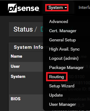
However, the problem is that even though a device in VLAN 99 would now know how to get to the internet, pfSense has no idea how to get back to our new network. We would be able to send packets to the internet from a system in the 10.99.10.0/24 subnet but that system would not be able to receive them from the internet. So, the next step is to tell the firewall how to get there. We are going to sign in to our pfSense appliance and go to System and then to Routing.
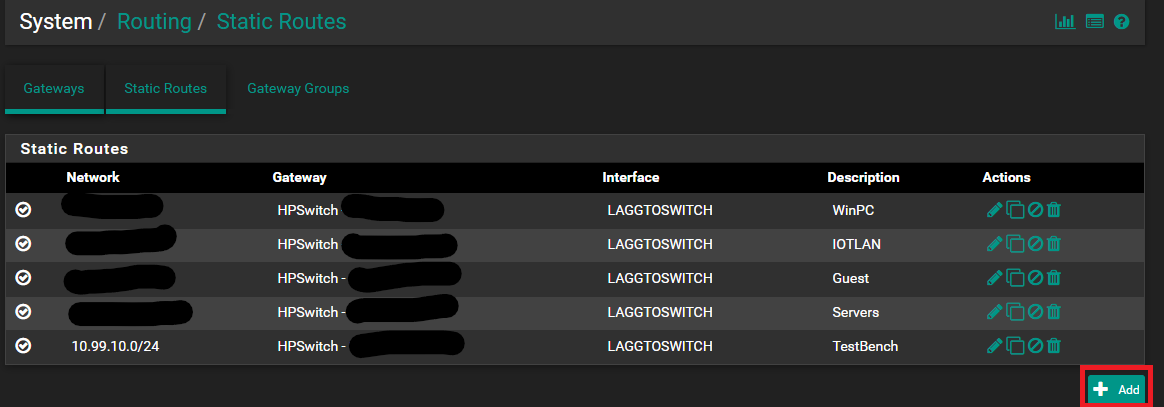
Once on that page, we need to locate the Static Route tab. It will list all of the existing routes. To add the new route we are going to press the + Add button at the lower right-hand corner.
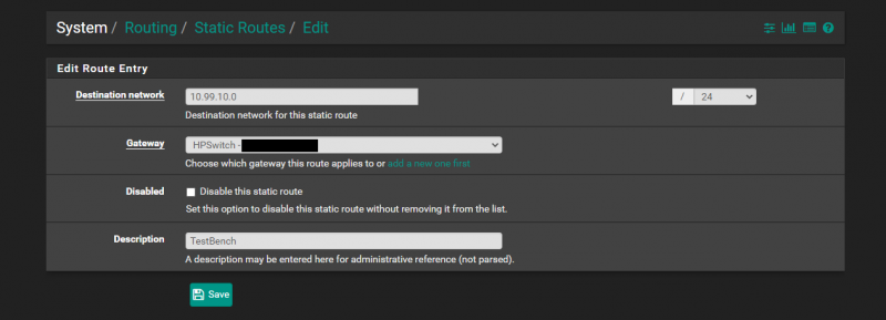
Once there, we need to define our route entry. What we are doing here is telling pfSense that to get to the network 10.99.10.0/24 we need to go to the gateway that is our HP core.
After having done all of those steps, we have created a routable network that we can use to get from our datacenter to and from the internet as well as other internal networks that we had not written an ACL to otherwise prevent.
Next, we are going to get to our 10GbE MikroTik switch setup for all of the iSCSI traffic in VMware vSphere.


The answer is always 42
The answer, is actually always 420.
You are both correct.
Answer to the Ultimate Question of Life, the Universe, and Everything
Yeah, but does anyone know the actual question?
Some of those add-on fans look like they need safety grilles to prevent loose fingers from being inserted among speedily rotating plastic blades. OUCH!
Yes, better cable management is needed.
Remember, “neatness counts, except in horsehoes and hand grenades”.
Nick, the most common Mikrotik external PSUs can be 24v .8A or 24v 1.2A depending on the market, here in South America the 1.2A is a lot more common on new equipment (rb760igs, lhg, etc) but there is a lot of equipment that comes with the .8A.
Correction: VLAN tagging allows you to carry multiple networks (Broadcast domains) on a single interface. This is often called Trunking. Link Aggregation is combining multiple ports (collision domains) into one logical interface. It is basically NIC teaming for switches. If you can help it use LACP as it fails in a more predictable way
Brian, I am not sure what you are correcting me on?
I believe there is a typo on page 3 under “Configuring our VLANs.” The second port is listed twice, where it should be and where the fourth port was expected.
Thanks for the articles series, I am enjoying them so far.
Comments are closed.