Configuring Sw(itch)OS
Now that our switch is successfully booted into SwOS, we can begin configuring it to meet the needs of our new datacenter.
SwOS is organized by tabs going across the top. To get us started, we are going to do three basic first steps which should be considered best practice, especially for security reasons.
- We are going to give it an IP address in the subnet we created above.
- We are going to set a password for the web interface.
- We are going to update it to the latest version.
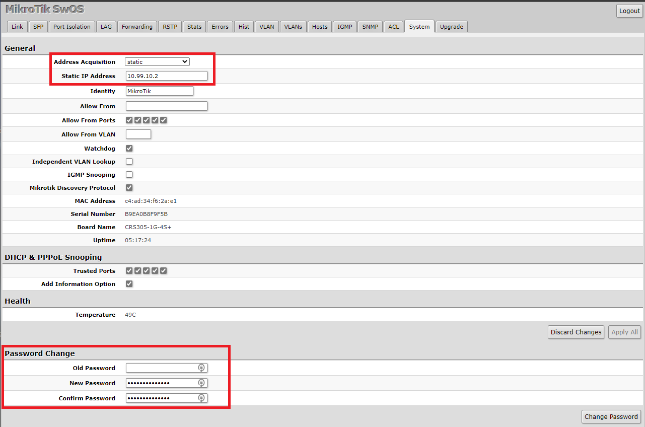
To do that we are going to first click on the System tab on the navigation bar. In the Address Acquisition drop-down menu, we are going to select Static. In the Static IP Address field, we are going to give it an IP of 10.99.10.2. Then we can press Apply All and we can reload this page by going to the new IP address http://10.99.10.2 in a web browser. At this point, you can unplug your laptop and go to any other workstation on your network to finish the config if you prefer.
Once we are back in the SwOS configuration, we are going to click on System tab again in the navigation bar. At the bottom of the page, we are going to leave Old Password blank, and under New Password and Confirm Password we are going to enter a new secure password. Click Change Password and the web page will then ask you to sign back in. Use admin and the new password you just set to proceed.
Next, we are going to click on the Upgrade tab in the navigation bar. If there is an update available for your switch you will see a higher version number listed under Latest Available Version than is listed under Current Installed Version. I’ve already updated mine, so the version numbers are the same. To kick off the update you are going to press Download & Upgrade. After it finishes, it will reboot and we will be ready to move on with our configuration.
Now, onto setting up our VLANs. We need to create two distinct subnets. This is done in order to follow VMWare’s guidance on how to properly prepare for ISCSI. ISCSI, or Internet Small Computer Systems Interface, is a network protocol (layer 4) that works on top of TCP. Its purpose is to provide block-level access to storage devices on remote systems. For our lab, we are connecting our VMWare host (the initiator) to TrueNAS (the target). used One of them will need to routable so that our VMs can get to where they need to go, while the other VLAN does not have to be. We only set one up to be routable in the Configuring your Core section, so the second VLAN we configure will be internal to the data center only.
Configuring our VLANs
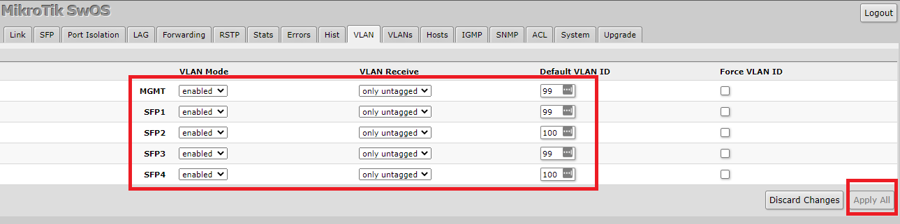
To begin this configuration we are going to click VLAN (not VLANs) on the navigation bar at the top of the SwOS management page. We are not going to configure any tagged VLANs, only untagged, or access ones.
Something we noticed about SwOS that differs from most switches we have worked with in the past is how it handles VLANs. There is a drop-down menu called “VLAN Receive” and by default it is set to “Any”. What this means is that if you have VLANs tagged on the other side (such as the uplink from our HP), you do not need to define them on the Mikrotik side. SwOS will just pass the tagged frames along to the other ports on the switch. This is not usually expected behavior and can cause security concerns. Because of that, we are recommending you turn this feature off.
- For MGMT we are going to set VLAN Mode to Enabled, we are going to set VLAN Receive to only untagged and for the Default VLAN ID we are going to specify 99.
- For SFP1 we are going to set VLAN Mode to Enabled, we are going to set VLAN Receive to only untagged and for the Default VLAN ID we are going to specify 99.
- For SFP2 we are going to set VLAN Mode to Enabled, we are going to set VLAN Receive to only untagged and for the Default VLAN ID we are going to specify 100.
- For SFP3 we are going to set VLAN Mode to Enabled, we are going to set VLAN Receive to only untagged and for the Default VLAN ID we are going to specify 99.
- For SFP2 we are going to set VLAN Mode to Enabled, we are going to set VLAN Receive to only untagged and for the Default VLAN ID we are going to specify 100.
Once we have made those changes, we are going to press Apply All.
One thing worth noting at this point is the difference between VLAN 99 and VLAN 100 in our configuration. The network at VLAN 99 is untagged on the uplink, which means it is accessible at layer 2 to any device also on VLAN 99 on our HP switch. Additionally, it is a routable network that our HP switch knows about. This means it would be accessible on any other network in our larger environment unless there was an ACL written to exclude it. The network in our VLAN 100, conversely, is only available on the two ports which we defined here.
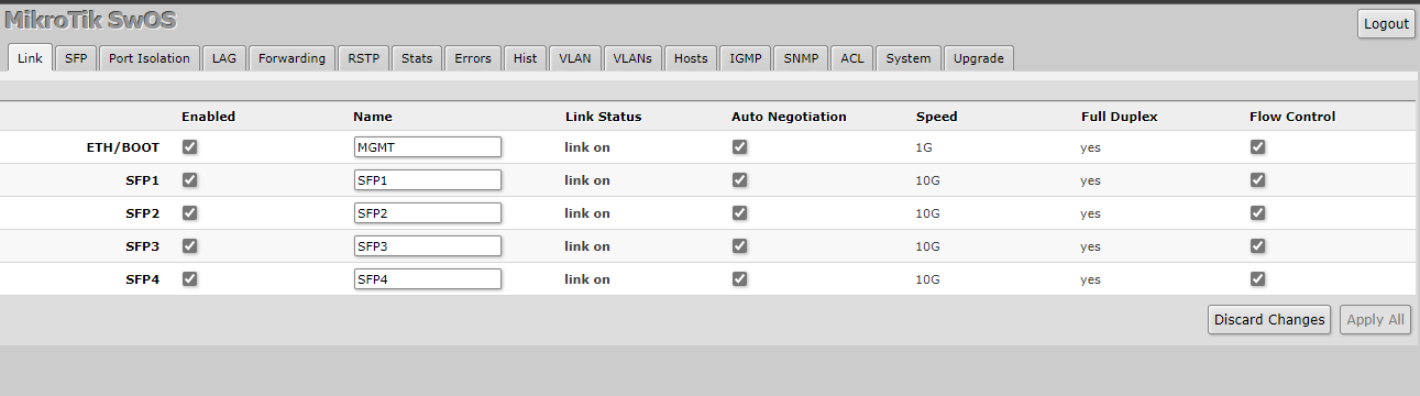
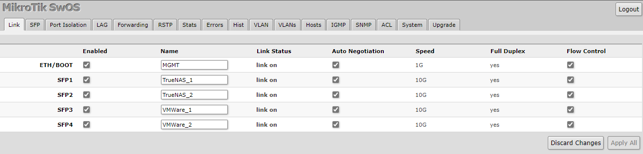
Finally, we are going to go to the Link tab on the navigation bar on the SwOS management page. Now we are going to name our interfaces as to what their purpose is so that when we come back to this system, or if someone else comes to it later, they will know what is what. After you type what names you would like, press Apply All.
Some Downsides of the Mikrotik CRS Platform
We realized at this point there were a few things worth mentioning about the CRS platform and the CRS305 in particular. In our workflow, we noticed that Mikrotik does not support LLDP on SwOS (it does on RouterOS.) There are not any options to turn it on/off, and it does not show up in the LLDP neighbors on our HP switch. Link Layer Discovery Protocol (LLDP) is a vendor-agnostic feature on most managed switches that are used for advertising a device’s identity, capabilities, and neighbors. Without LLDP, it is very difficult for a network administrator to know that another switch is connected to a port on their network. This may be an immediate disqualifier for some, and so it is worth mentioning.
Additionally, we had some weird quirks when using 10Gbase-T transceivers on the CRS305. It seemed to work reliably with only 3 of our 4 adapters. At first, I thought one of the adapters was bad, then I thought maybe one of the SFP+ cages was damaged in some way. The problem was that the same port that would not work each time I tried to use it. What was strange was that the switch saw the modules in the SFP tab just fine:
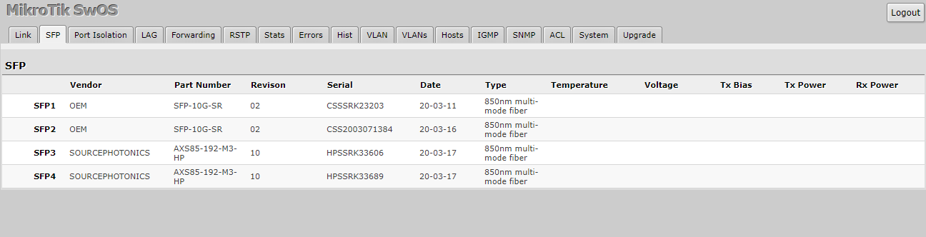
But what was happening was no matter what I did the Link Status would stay off on the Link tab, and I would not get any lights. I even tried another NIC on the server that was plugged into it. In the end, I resigned to using two DAC cables and two 10G BaseT transceivers, and it has been stable ever since.
The only assumption I can make about this problem is that it is a power budget limitation. During my testing, I tried powering it via the included power brick and also via POE. The fact remains, 10Gbase-T simply put uses more power than a SFP-10G-SR laser or a DAC. The CRS305 only has about 15 watts of power to work with, while testing we saw it drawing about 12 watts of power over POE. The included power brick is a 24v 800mA adapter, which gives us about 19 watts. Each 10Gbase-T transceiver can draw anywhere between 2 and 3 watts alone, not leaving much headroom for the switch itself.
Next, let us discuss some of the parts we could do better, before concluding with our final words.


The answer is always 42
The answer, is actually always 420.
You are both correct.
Answer to the Ultimate Question of Life, the Universe, and Everything
Yeah, but does anyone know the actual question?
Some of those add-on fans look like they need safety grilles to prevent loose fingers from being inserted among speedily rotating plastic blades. OUCH!
Yes, better cable management is needed.
Remember, “neatness counts, except in horsehoes and hand grenades”.
Nick, the most common Mikrotik external PSUs can be 24v .8A or 24v 1.2A depending on the market, here in South America the 1.2A is a lot more common on new equipment (rb760igs, lhg, etc) but there is a lot of equipment that comes with the .8A.
Correction: VLAN tagging allows you to carry multiple networks (Broadcast domains) on a single interface. This is often called Trunking. Link Aggregation is combining multiple ports (collision domains) into one logical interface. It is basically NIC teaming for switches. If you can help it use LACP as it fails in a more predictable way
Brian, I am not sure what you are correcting me on?
I believe there is a typo on page 3 under “Configuring our VLANs.” The second port is listed twice, where it should be and where the fourth port was expected.
Thanks for the articles series, I am enjoying them so far.
Comments are closed.