Networking Setup – The Mikrotik CRS305-1G-4S+IN
Before we start, it is worth noting that our new Mikrotik switch and servers are physically located in a different area than the MDF that we talked about above. This is called an IDF or intermediate distribution frame. This is not a requirement it is just how our network is configured.
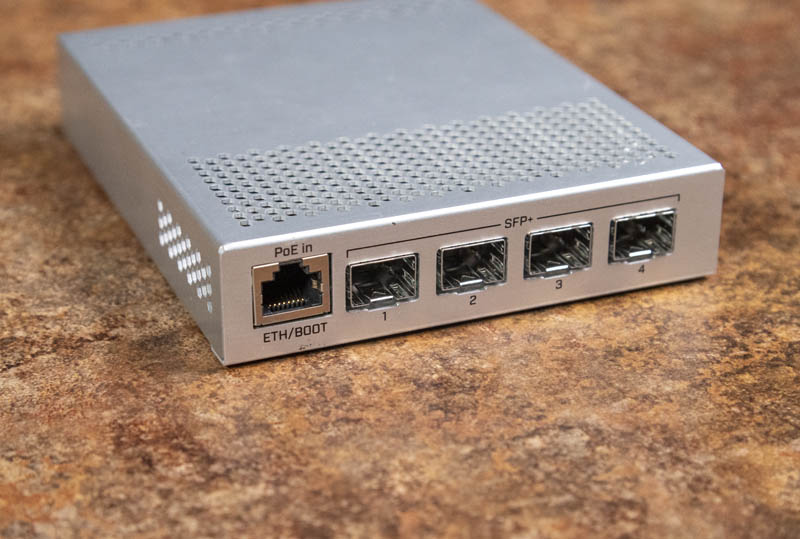
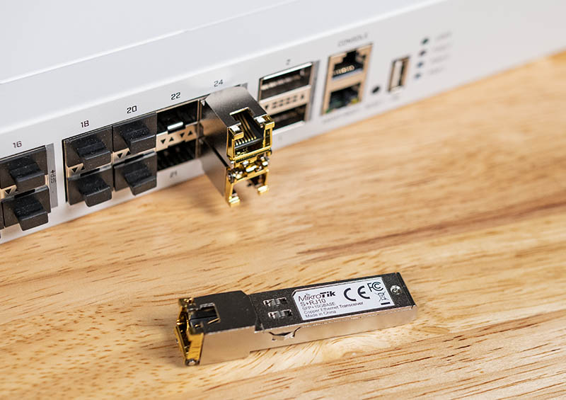
The MikroTik CRS305-1G-4S+IN is a 10-gigabit switch that uses SFP+ cages as a medium to communicate, in comparison to the more traditional RJ45. You can use various different types of modules, formally known as transceivers (and also informally known as GBICs). These cages were created originally to facilitate transceivers which sent and received data over fiber-optic cables using lasers. Generally, you would use these types of transceivers when communicating between the switch and a closet in another area in the building.
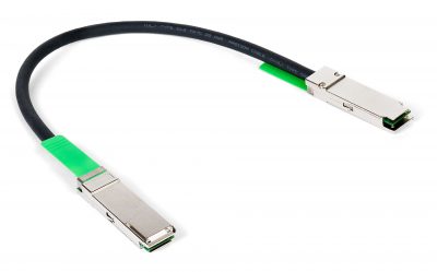
Direct Attach Copper (also known as DACs or Twinax) transceivers are also very common and are generally used when connecting systems inside of a rack.
Additionally, 10G BaseT transceivers exist, which convert an SFP+ cage to a more traditional RJ45 socket.
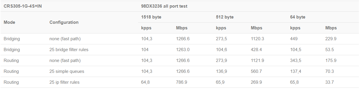
The CRS305 is a managed switch that has layer 3 features available out of the box. What that means is that it is technically capable of doing things like routing. The problem is, however, that these features are all done in software on the CPU. Layer 3 switches in the enterprise (Like our HP Switch) typically have a dedicated ASIC to do the packet pushing. An ASIC is an application-specific integrated circuit, and compared to a general-purpose CPU it is capable of much more efficiently completing tasks. The CRS305 is is a sub 200 dollar device so it is not really fair to compare it to our HP Switch which costs substantially more. Nevertheless, the CPU in the CRS305 is nowhere near powerful enough to be capable of doing routing for us and so we are treating it as a layer 2 only managed switch.
The CRS305 like many of the newer Cloud Router Switch products has a nifty feature, dual-operating systems. Out of the box you get both RouterOS as well as the more paired down SwOS. Since SwOS does pretty much all we need with what is in my opinion a much less clunky UI, we chose to use it instead. We are going to start by signing into the switch and putting it into SwOS mode. Personally, I think this device should ship in that configuration.
Initial Switch Configuration
To get us started, we are going to uplink our CRS305 to the rest of our network at this point. We are going to start by plugging the 1-gigabit management port on the CRS305 into the port we pre-programmed on our HP Switch earlier. In our case, it is being powered by POE. Power Over Ethernet is a way in which we can use switches to power end-point devices such as phones, cameras, or access points. In this case, the CRS305 is a switch, but it supports POE input. The switch also comes with a power brick, and actually supports dual, redundant power using two of them.
There is no serial console port so we need to plug a laptop or PC into an ethernet port on our CRS305 to do the initial configuration. All the ports on a CRS switch are on VLAN 1 by default so it does not matter which port you choose. However, since we were using the management interface already, we needed to use a 10Gbase-T transceiver into an SFP+ cage. You will then need to configure your device to be in the same network that the CRS305 is in default. Give your device any IP address in the 192.168.88.0/24 subnet except 192.168.88.1. Then open a browser and go to the management interface http://192.168.88.1.
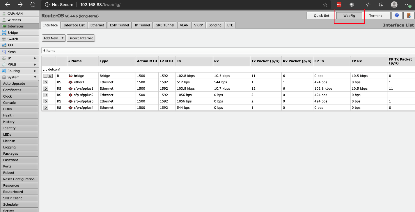
Once there, you will be prompted for a username and password. The default username is “admin” and the password is blank. After entering the credentials you will land on the dashboard for Quick Set. Instead of following this wizard, we are going to find the WebFig button and click on that.
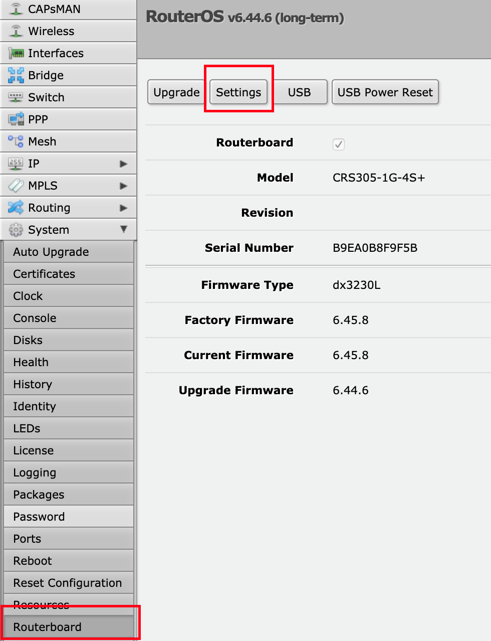
After we’ve done that, the next step is to find System on the left-hand menu. If you click on it, it will expand the tree. We are looking for the not-so-obvious Router Board button and we will press that. Once on that page, we are going to click into the Settings tab.
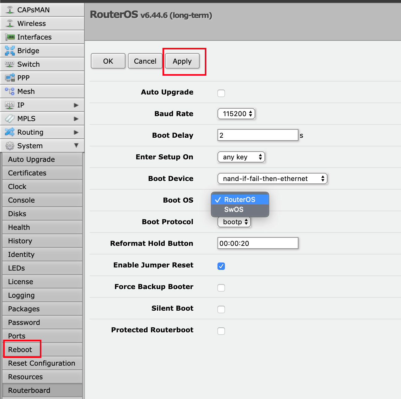
Now that we are on the settings page, we can scroll down to the Boot OS menu item. When you click on it, you can choose between RouterOS and SwOS. We are going to select SwOS and press Apply. This setting is only applied on boot time, so to make the switch load SwOS, we need to press Reboot. When it comes back up, it will prompt you for your credentials again, and you will be in SwOS.
Now what we have switched to MikroTik SwOS, we are going to configure the switch for VMware.


The answer is always 42
The answer, is actually always 420.
You are both correct.
Answer to the Ultimate Question of Life, the Universe, and Everything
Yeah, but does anyone know the actual question?
Some of those add-on fans look like they need safety grilles to prevent loose fingers from being inserted among speedily rotating plastic blades. OUCH!
Yes, better cable management is needed.
Remember, “neatness counts, except in horsehoes and hand grenades”.
Nick, the most common Mikrotik external PSUs can be 24v .8A or 24v 1.2A depending on the market, here in South America the 1.2A is a lot more common on new equipment (rb760igs, lhg, etc) but there is a lot of equipment that comes with the .8A.
Correction: VLAN tagging allows you to carry multiple networks (Broadcast domains) on a single interface. This is often called Trunking. Link Aggregation is combining multiple ports (collision domains) into one logical interface. It is basically NIC teaming for switches. If you can help it use LACP as it fails in a more predictable way
Brian, I am not sure what you are correcting me on?
I believe there is a typo on page 3 under “Configuring our VLANs.” The second port is listed twice, where it should be and where the fourth port was expected.
Thanks for the articles series, I am enjoying them so far.
Comments are closed.