Gigabyte E251-U70 Internal Hardware Overview
Inside the system, we get a standard LGA3647 socket for first and second-generation Intel Xeon Scalable processors. We tested both generations and they worked in the socket.
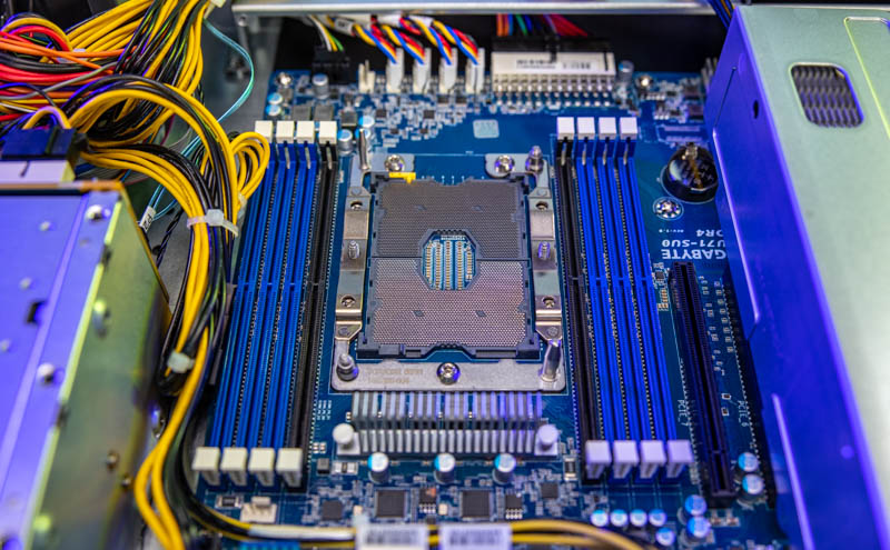
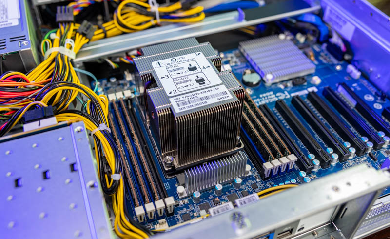
The system has a 2U heatsink (and an air shroud you can see in the external overview section) that is able to cool up to 205W TDP processors. The eight DIMM slots take DDR4 memory and one can use Optane DCPMM or PMem 100 modules in this system.
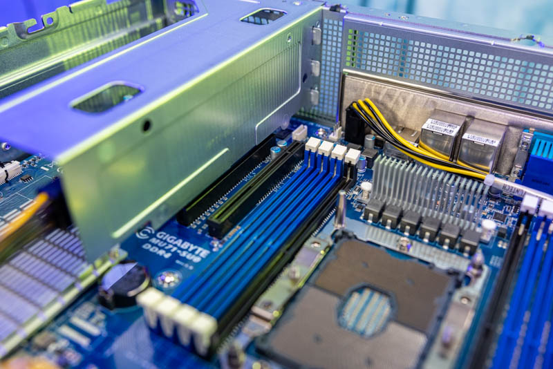
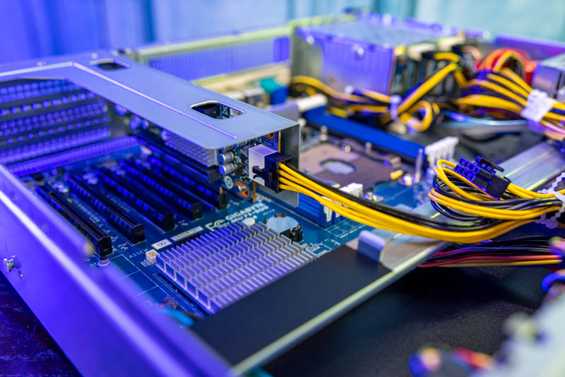
The next big feature outside of the CPU is the PCIe configuration. Something we noticed is that there is a single PCIe slot that does not have an external I/O mounting point. It feels like this slot could be better utilized in the system since there is not a standard way to secure a card in this slot.
In the external hardware overview, you may have seen three I/O expansion slots on a riser. These full-height slots are connected to two PCIe Gen3 x16 slots. Between the slots, one can see a heatsink for a Broadcom PEX8747 PCIe switch. This allows a single PCIe x16 slot to be used with two PCIe x16 slots on the riser. The slot closest to the riser gold fingers is designed for a high-speed NIC/ DPU, the top slot is designed for a GPU. This is specifically the design for the NVIDIA Ariel 5G vRAN platform and NVIDIA has the software to do a lot of the processing on the NIC/ DPU and GPU directly over PCIe instead of having to go back to the host. That is the primary reason for this design.
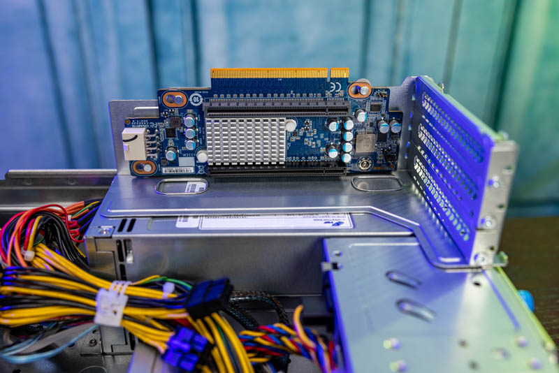
One may also notice that there is a power connector on the riser. There is an external power connector because we have two x16 slots as well as the PCIe switch. This power connector is required. We inadvertently tested not having this power cable plugged in with two very low power NICs and they did not power on. It seems as though this is powering the PCIe switch in this design which is why it is required.
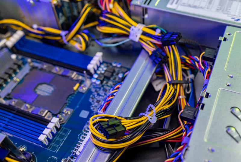
Since this system is designed for GPUs, we get a healthy set of GPU power connectors cabled here. Note: we pulled them out of their cable channel for a better look.
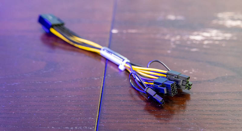
There was a small but nice feature in the box. The system came with a power adapter. While the system has primarily data center GPU PCIe power connectors, the splitter adapter allows one to connect a standard desktop/ workstation device and power it in this system. This is a small but welcome feature if ever one wanted to use a GPU with the alternate power inputs.
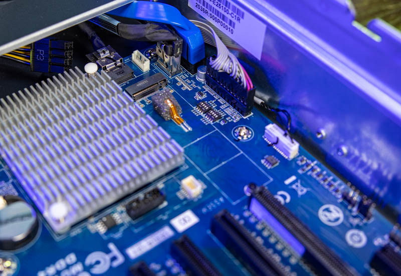
Here is the motherboard with the PCIe riser and power cable removed. On the subject of power, the ATX power input is horizontal in the leading edge of the motherboard (bottom of the below picture.) The CPU power is not on the top edge of the motherboard and is instead near the front I/O faceplate with airflow being blocked by the faceplate anyway. This is a small detail, but one that must be appreciated.
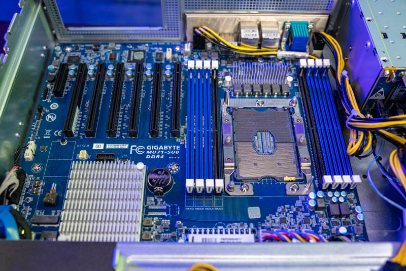
There is also a M.2 slot for storage on the motherboard. This only supports up to M.2 2280. One needs to remove the riser to get to this slot. We would have preferred if Gigabyte had a solution in the PCIe slot between the riser and the DIMM slots that could be used for this storage as it would be faster to service.
Overall, this is a fairly interesting 2U, single socket vRAN platform.
Next, we are going to look at the block diagram, management, and our test configuration before moving to the performance and power consumption figures.


The combination of a powered riser card with PCIe switch, rather than a passive riser using some higher-density proprietary edge connector, and a bunch of fully populated but mechanically unusable PCIe slots interests me. I definitely wouldn’t expect to see an active PCIe switch dragged in to a cost-optimized design that isn’t starved for CPU-provided lanes; and when pennies really need to be pinched even having the connectors populated isn’t a given.
Do you know if this system just shares a motherboard with one or more other Gigabyte units that require all the slots and it was cheaper to avoid SKU proliferation than it was to cut the redundant headers; or if there is a variant of the riser card module that just provides a bunch of half-height slots? The one slot closest to the RAM looks like it’s blocked by non-removable chassis metal; but the rest of them certainly look like they could be configured as half-height slots with an appropriate rear plate slotted in.
Who is this “one” I keep seeing in all STH articles? Neo?
Comments are closed.