
Advertisement


Home Server Server Systems Dell PowerEdge R770AP Review One Fast Intel Xeon 6 Server

Dell PowerEdge R770AP Review One Fast Intel Xeon 6 Server

0

Dell PowerEdge R770AP Internal Hardware Overview

We did not get a great shot going from the front backplanes to the rear, so instead here is the rear to the front with the fan modules out.
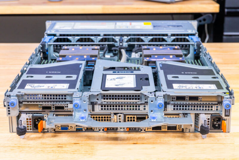
Complete open chassis view of Dell PowerEdge R770AP showing risers, processors, memory and fan bank positions
Complete open chassis view of Dell PowerEdge R770AP showing risers, processors, memory, and fan bank positions

Here is a quick look at that E3.S backplane providing connectivity to the storage.
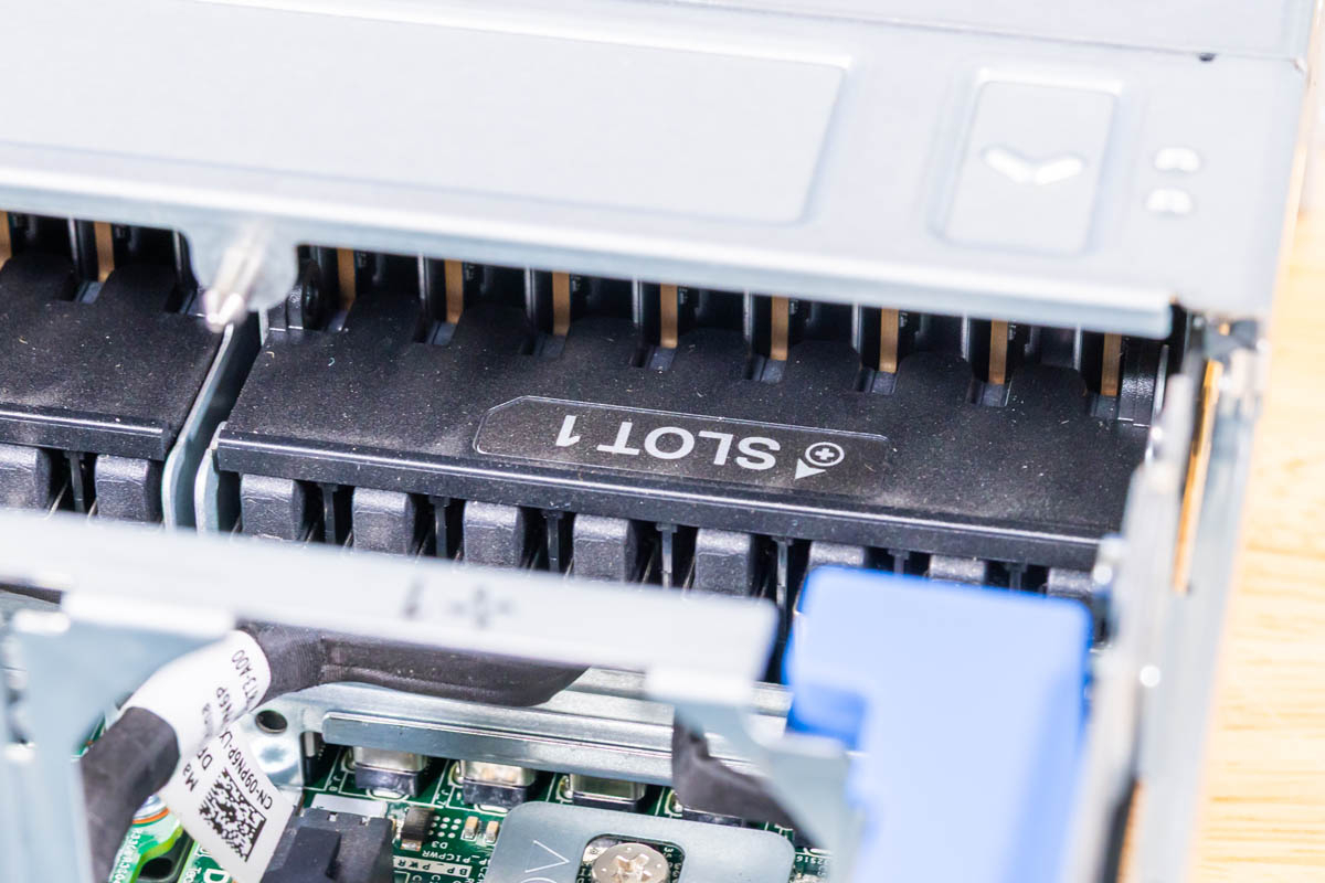
Internal slot1-labelled riser position in metal frame of Dell PowerEdge R770AP

Each of the 8-bay sections is given a slot number.
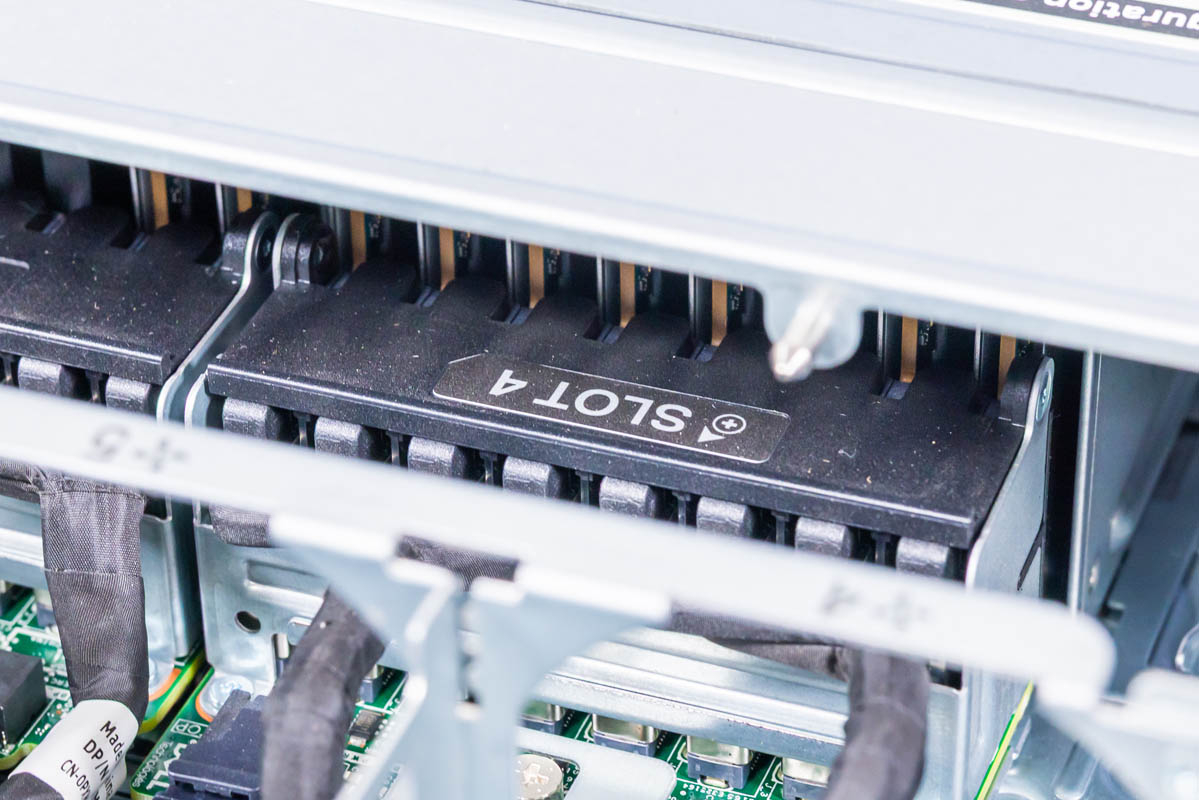
Internal slot4-labelled position and neighbouring riser frame in Dell PowerEdge R770AP
Internal slot4-labeled position and neighboring riser frame in Dell PowerEdge R770AP

Here is the other side.

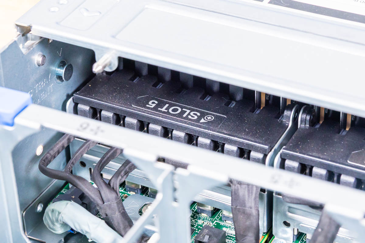
Internal slot5-labelled position with cable and structural bracket in Dell PowerEdge R770AP rear expansion area

Behind the front storage section sits an internal fan partition with six fans. This is the primary cooling partition for the chassis, separating the drive area from the compute section and keeping airflow predictable across both zones.
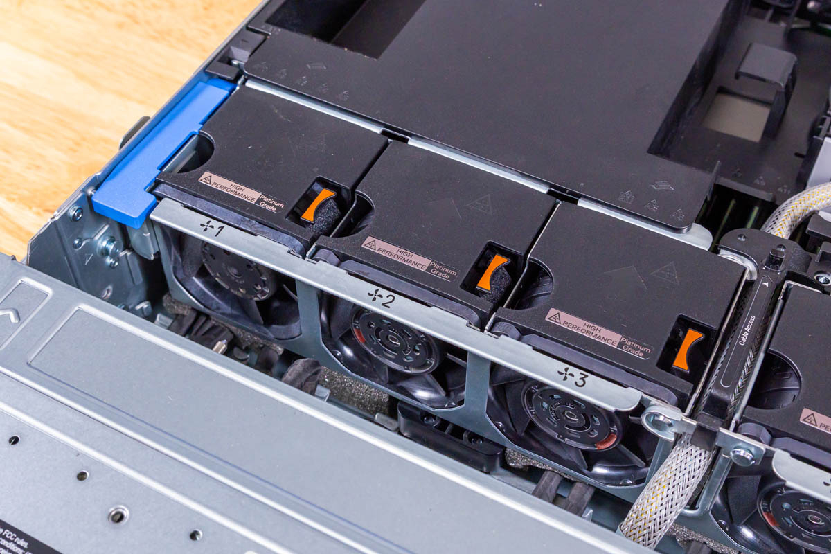
Installed six-position fan bank with black air shroud behind front storage area in Dell PowerEdge R770AP

Dell has cable throughways in this partition that help keep airflow through the fans and not leaking around the sides.
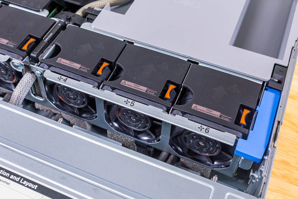
Opposite half of installed fan bank on Dell PowerEdge R770AP showing fans numbered 4, 5 and 6

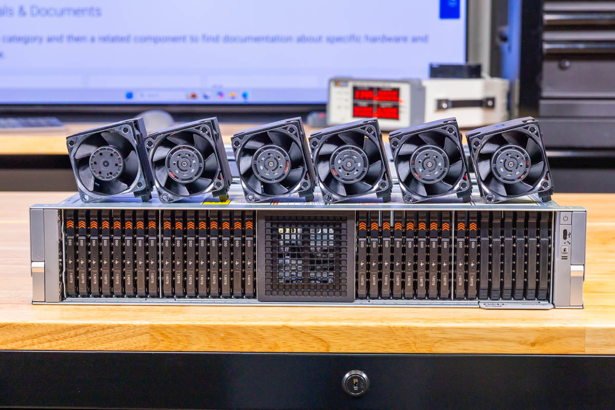
Here is a look at the six fans.

Six removed hot-swap fan modules from Dell PowerEdge R770AP lined up together

These Sunon units have hot swap connectors to make it easy to replace fans.
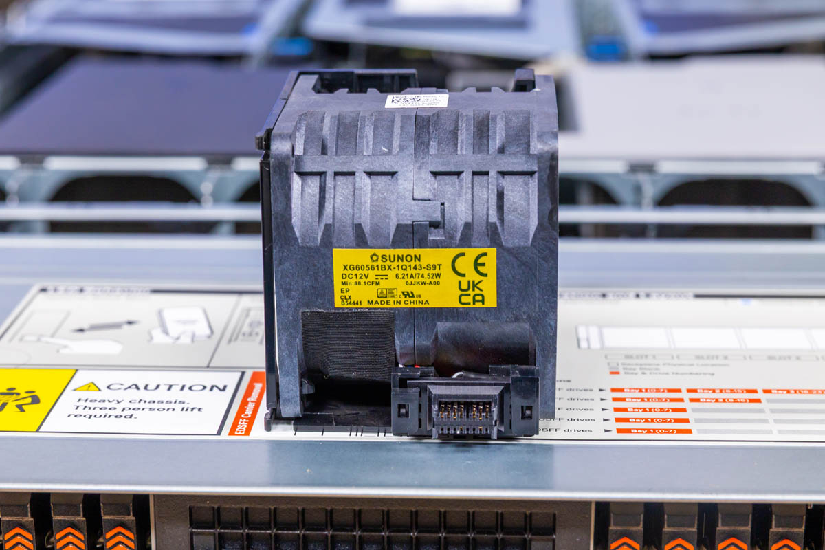
Single Sunon fan module closeup with connector and latch from Dell PowerEdge R770AP
Single Sunon fan module close-up with connector and latch from Dell PowerEdge R770AP

With the fans out, you can see the MCIO cables running from the motherboard to the storage up front.
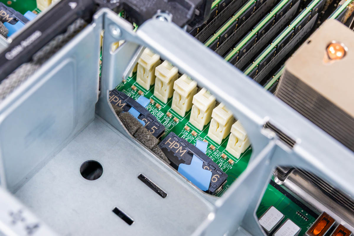
Row of pale headers near system board front with HPM/PWR51 cable guide label on Dell PowerEdge R770AP

The cable channels also allow these front MCIO and drives to reach the rear of the chassis.
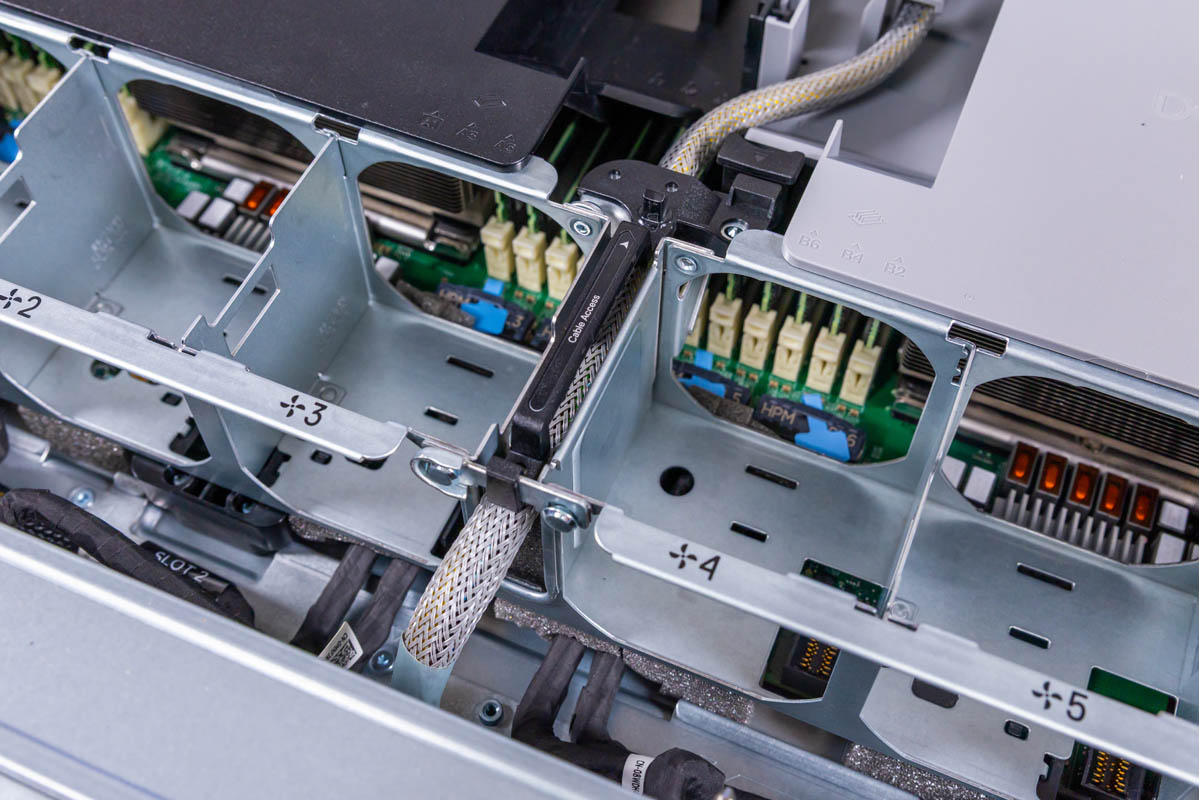
Braided cables following labelled metal channels and brackets near fan partition in Dell PowerEdge R770AP
Braided cables following labeled metal channels and brackets near fan partition in Dell PowerEdge R770AP

Two Intel Xeon 6900 series processors feature substantial silver heatsinks with copper heat pipes. DDR5 DIMMs sit beside and between the processor positions in this air-cooled 2U system design.
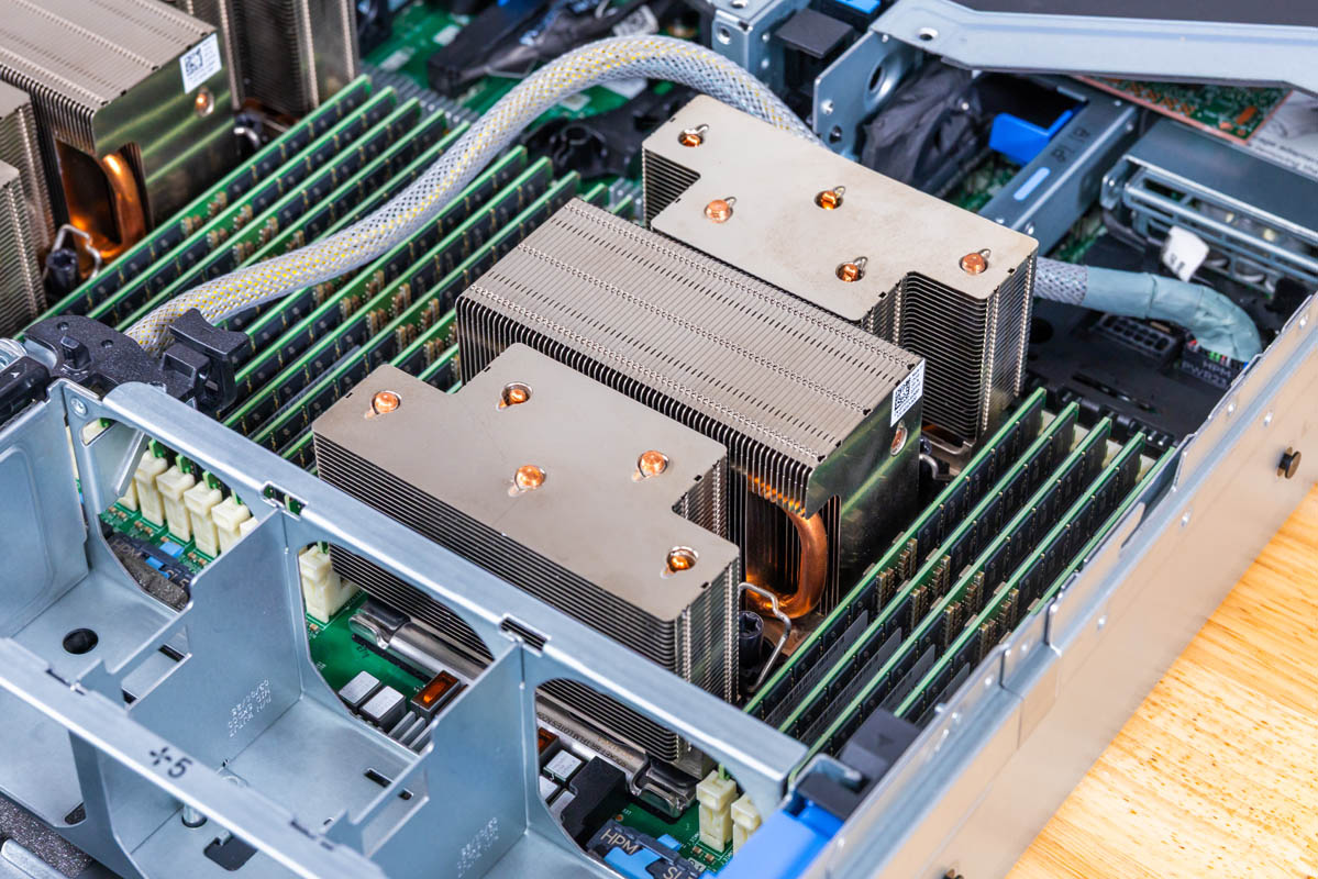
Two silver CPU heatsinks with copper heat pipes and DDR5 DIMMs beside them in Dell PowerEdge R770AP

If you think these heatsinks are big, just wait for what we will show you in a few days.
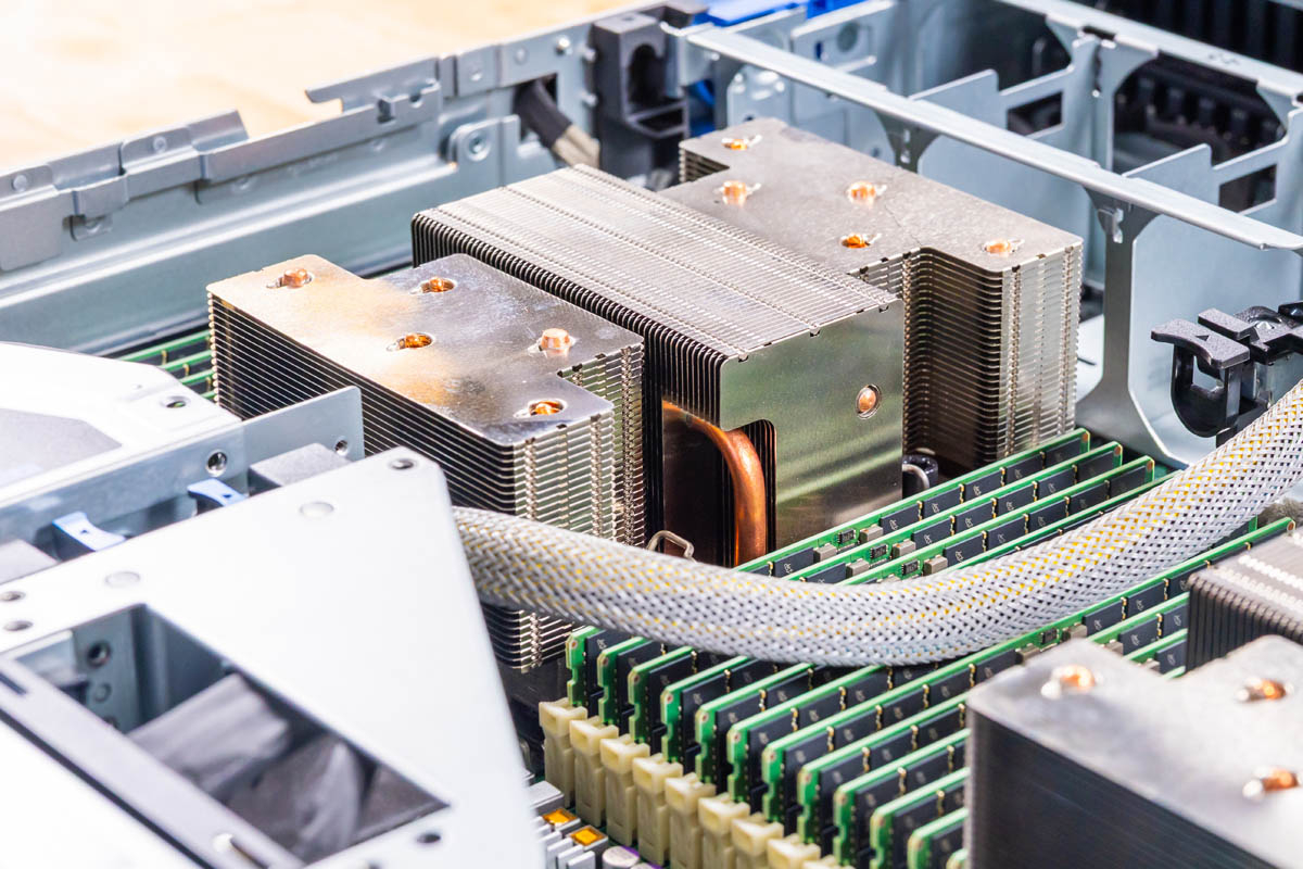
Heatsink side view showing copper heat pipes running from fin stacks toward base on Dell PowerEdge R770AP

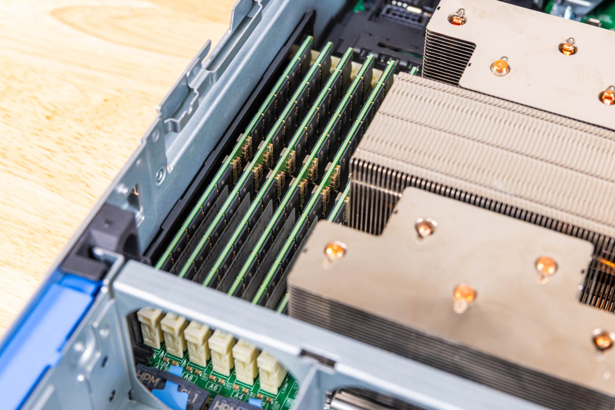
The memory layout is another area where the PowerEdge R770AP diverges most visibly from the standard PowerEdge R770, which we reviewed last year. Each processor gets twelve DDR5 channels with a single DIMM per channel (1DPC), giving 24 total slots across both sockets. This memory architecture differs from the R770’s eight channels per socket with two DIMMs per channel. The -AP offers more channels per socket but fewer total DIMM slots (24 versus 32) in this configuration.
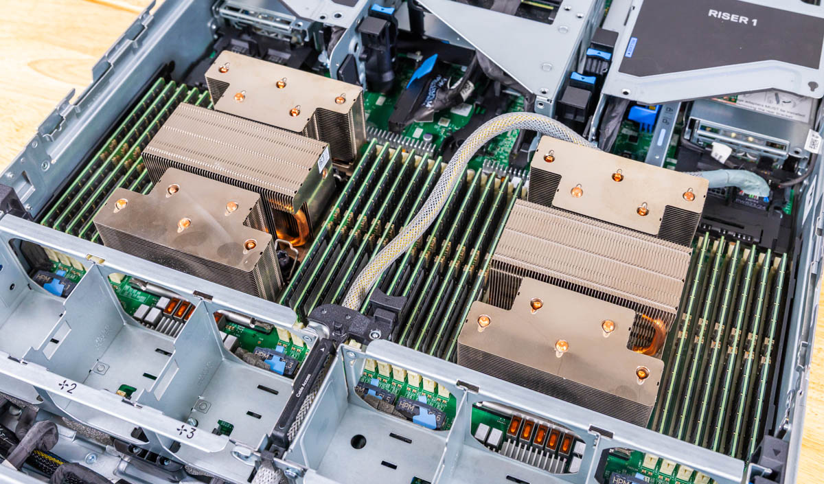
24 populated DDR5 DIMM slots around two CPUs in Dell PowerEdge R770AP, 12 per CPU at one DIMM per channel

If you have seen the PCIe Gen6 servers, the DDR5 DIMM slot pitch here seems luxurious in comparison since there are “only” 24 DIMMs next to the two sockets. This is less of a challenge in this generation, but it ramps up considerably in the next generation, just getting airflow through the spaces between the DIMMs.
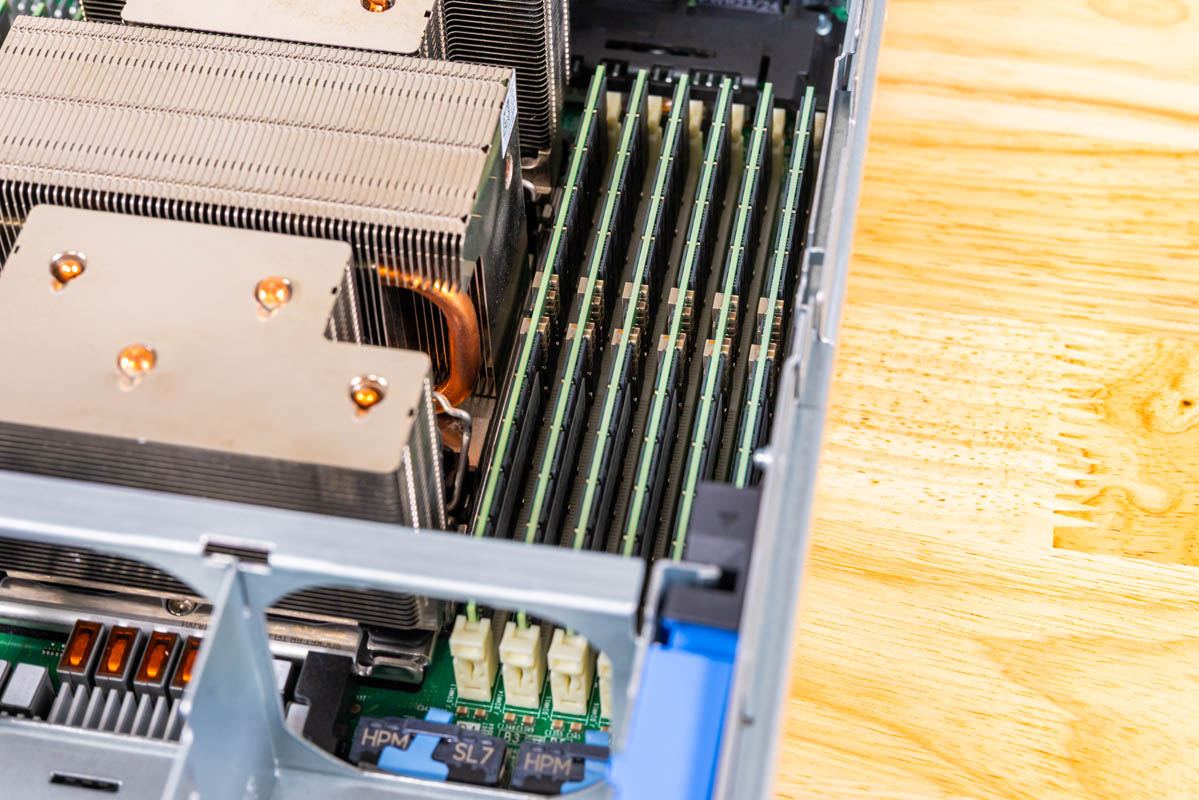
Closer view of DDR5 DIMMs and copper heat pipes along one CPU bank in Dell PowerEdge R770AP

In this platform, since it is a Xeon 6900P platform, you can use either DDR5 ECC RDIMMs or MRDIMMs. The MRDIMMs are useful if you just need extra memory bandwidth.
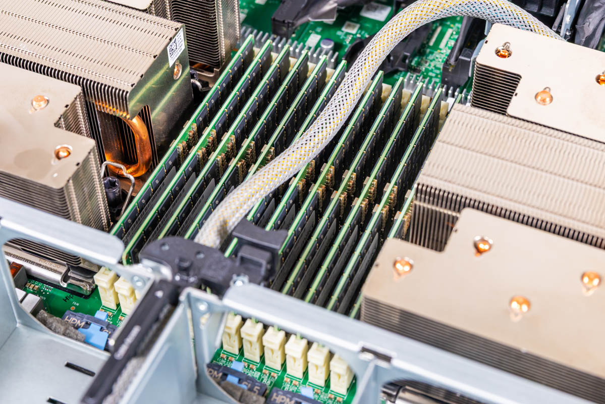
DDR5 banks between CPUs with braided cable routed above on Dell PowerEdge R770AP

Here is a look at the other side.

Outer CPU DIMM bank closeup showing one slot per memory channel on Dell PowerEdge R770AP
Outer CPU DIMM bank close-up showing one slot per memory channel on Dell PowerEdge R770AP

Moving toward the rear, we reach the expansion architecture. Here you can see the risers labeled 1, 3, and 5 installed across the back edge, with positions for 2 and 4 adjacent to them. Each module carries a handle and blue release latch, and together they represent Dell’s modular approach to rear I/O. It also shows off how Dell has service guides and great labeling throughout the system.
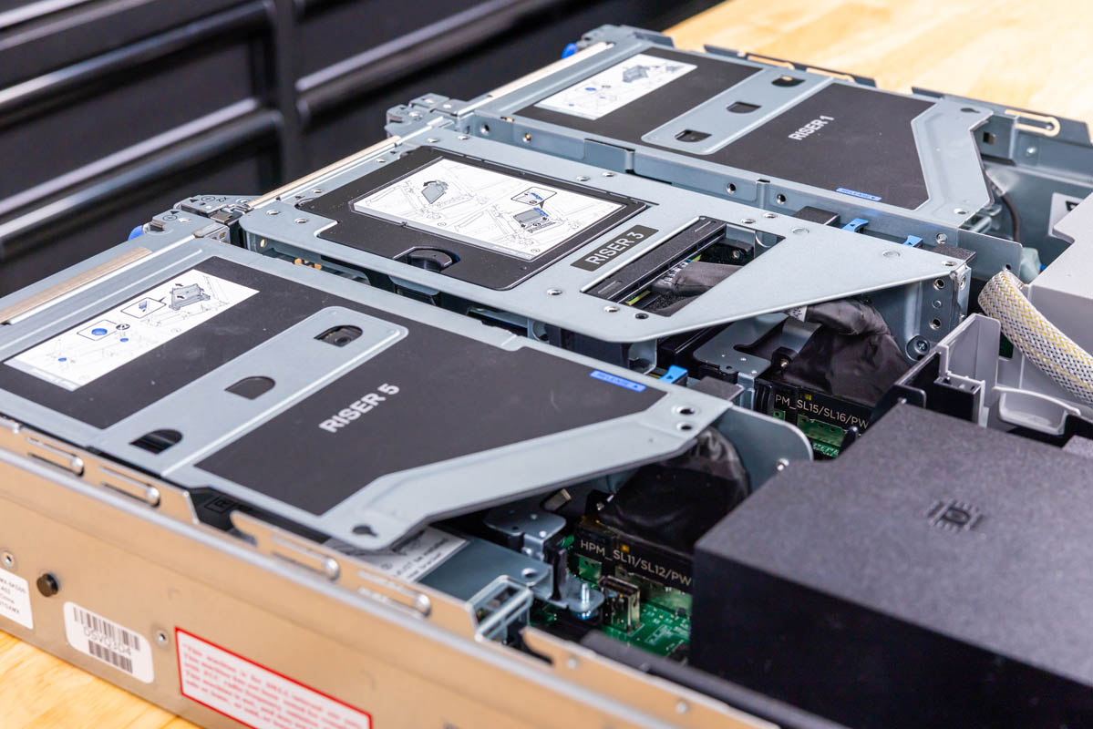
Wide view of rear risers labeled 1, 3 and 5 with adjacent 2/4 positions, handles and blue releases in Dell PowerEdge R770AP

Since these are very configurable, we thought we would just show you what they look like in this system.
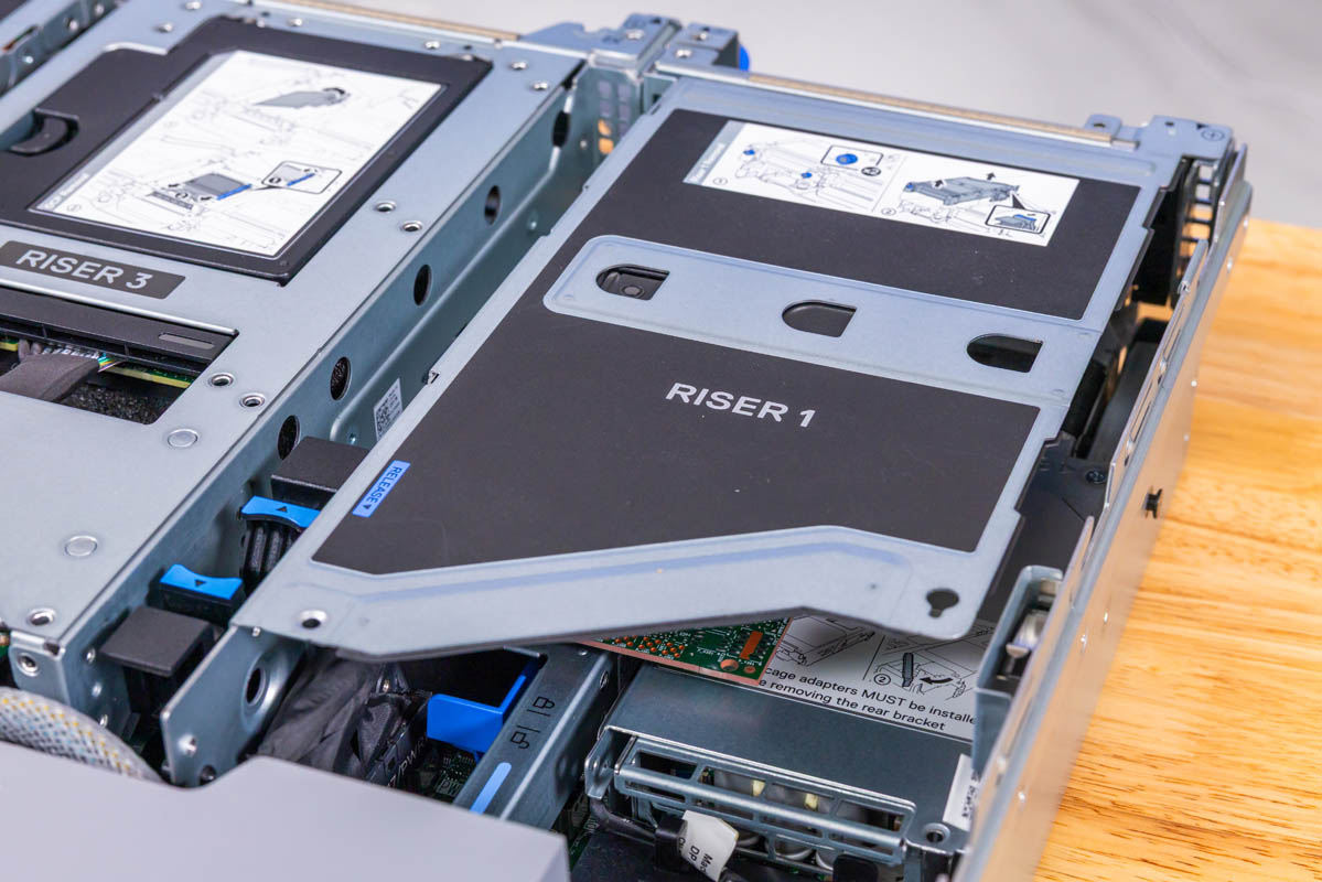
Riser1 installed at back edge of Dell PowerEdge R770AP with metal cover printed installation diagram

Here is a look at Riser 1 outside of the system:
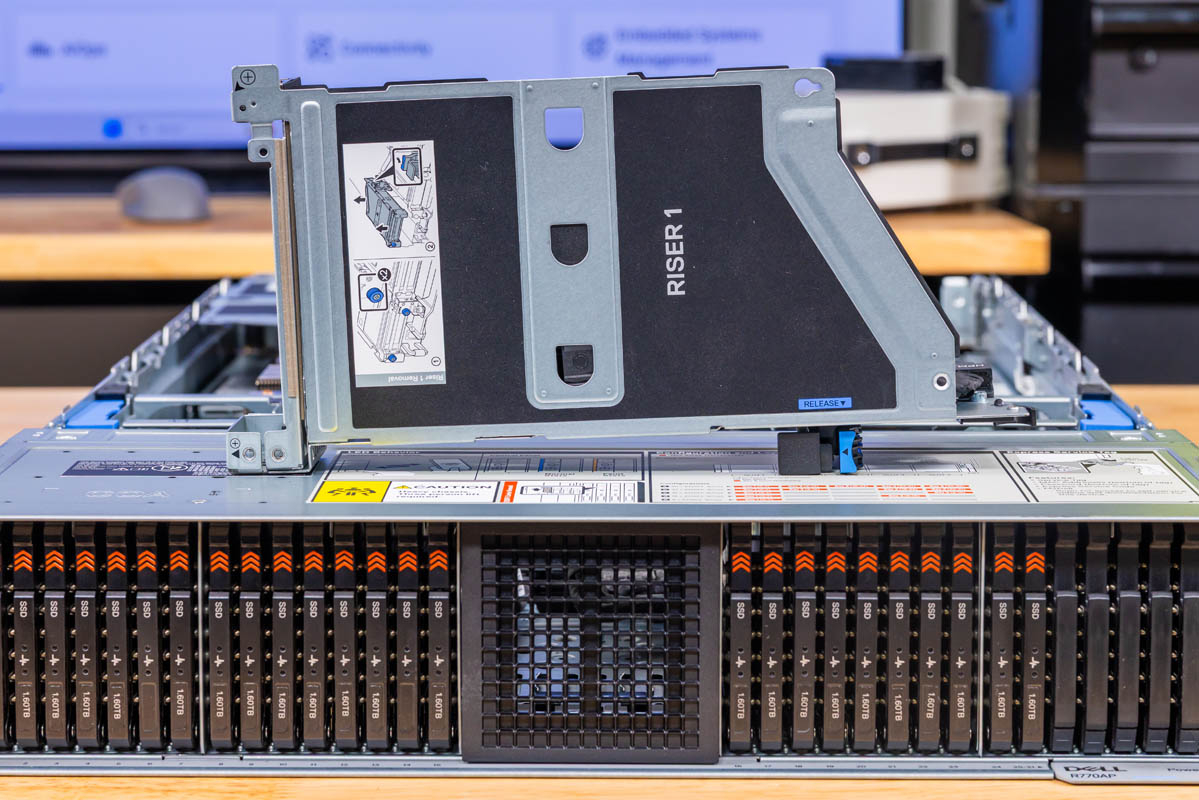
Removed Riser1 from Dell PowerEdge R770AP showing cover, handle and installation diagram side

Also, here is flipping it over, where you can see the motherboard connector and the card built-in.
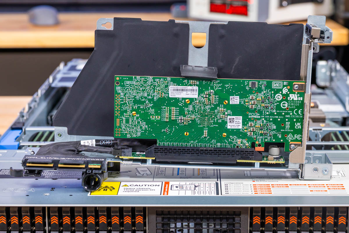
Riser1 removed from Dell PowerEdge R770AP exposing green riser board, low edge connector and metal frame

Under the main risers, there is often another layer of risers.
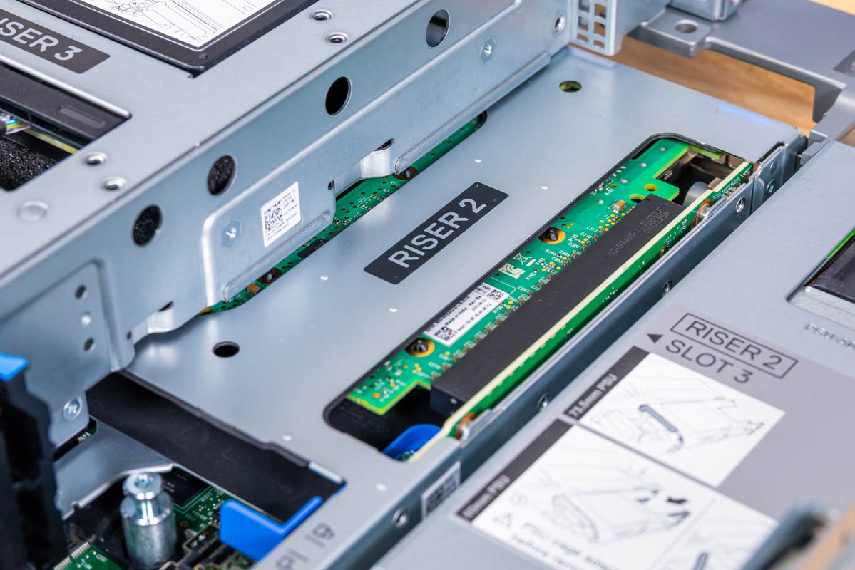
Riser2 label on small horizontal green board near Riser1 in Dell PowerEdge R770AP rear expansion area

Riser 3 has something really neat. Instead of just being a PCIe riser, you can see an OCP NIC 3.0 slot.
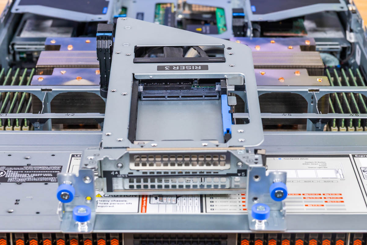
Riser3 removed or tilted view exposing connector within module on Dell PowerEdge R770AP

While it is an SFF with an internal latch design, not an SFF with a pull-tab design, it is still a neat way to get another OCP NIC 3.0 slot in a system like this.
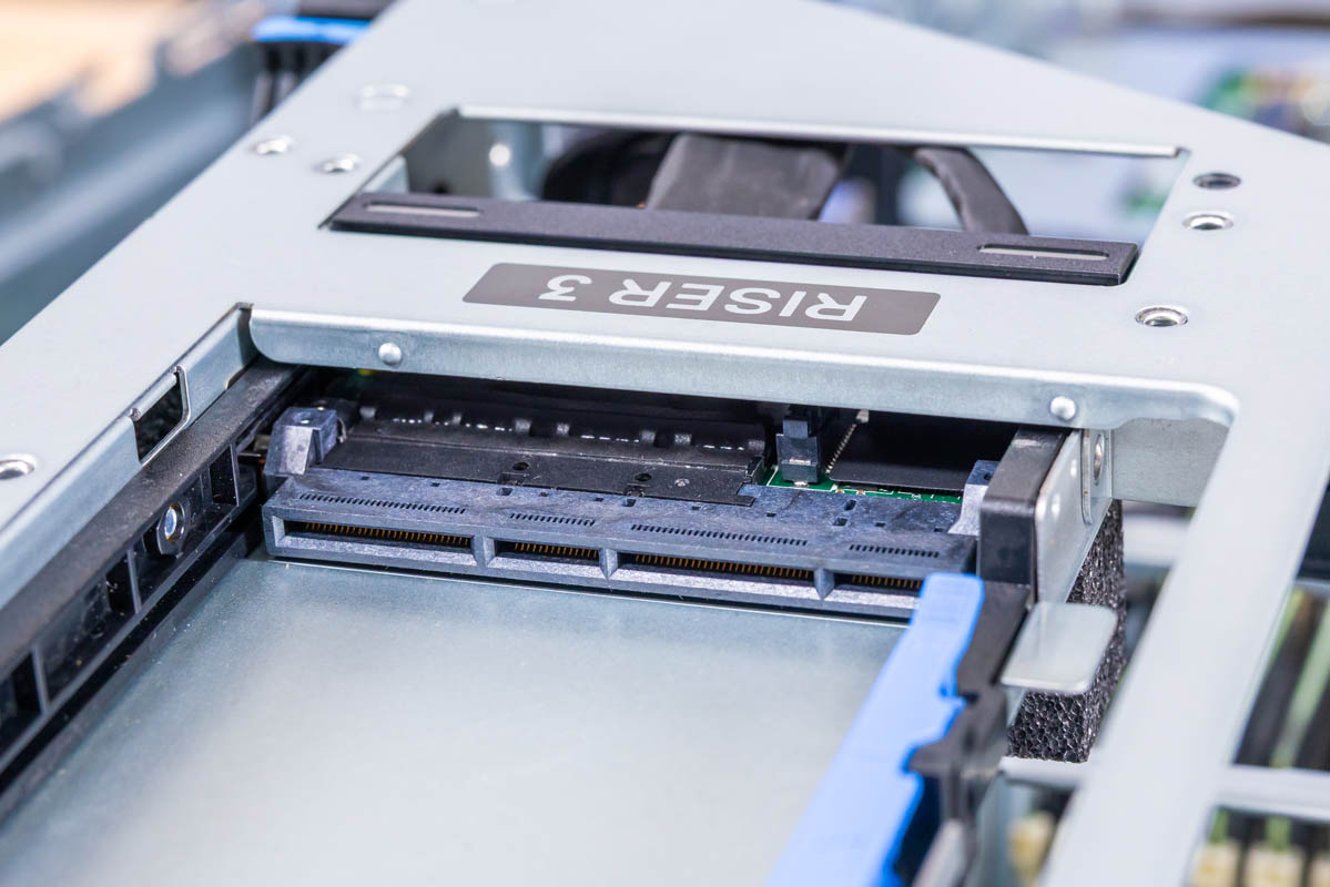
Riser3 lifted out revealing long slot and black alignment connector on Dell PowerEdge R770AP system board

Pulling these out, we can see Riser 4 underneath.
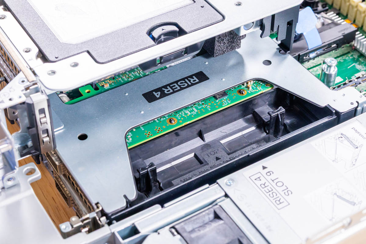
Central riser removed from Dell PowerEdge R770AP exposing green board, PSL3 label and nearby HPM power/slot connector

Riser 4 appears as another small green board beside the central riser, with nearby connectors. This view shows the module’s separate physical position within the chassis layout. Once we get further inside, we can see BOSS module and more.
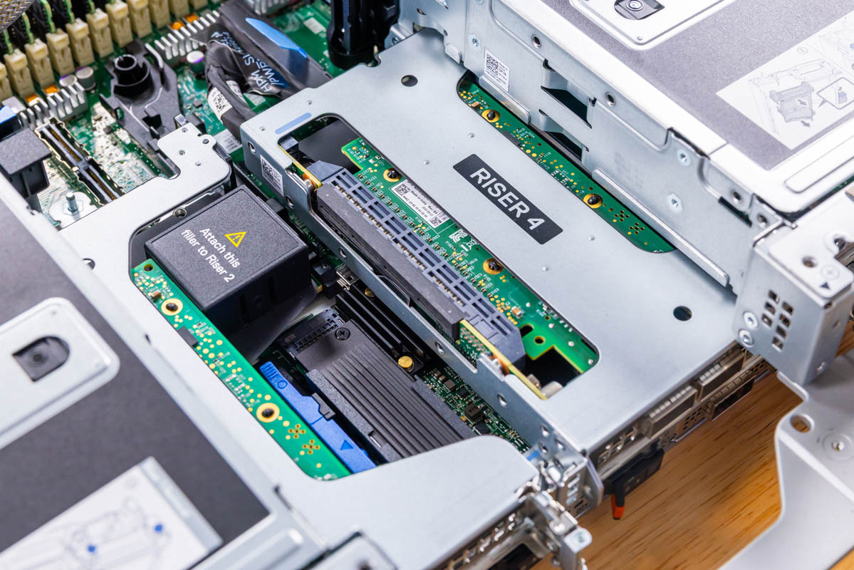
Small Riser4 green board installed beside central riser with power connectors in Dell PowerEdge R770AP

Riser 5 is the final installed module in our configuration.
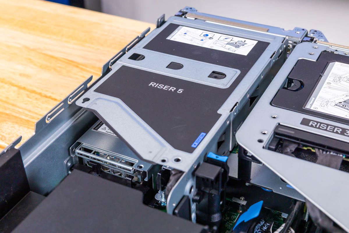
Riser5 metal module installed next to central riser with own handle and diagram on Dell PowerEdge R770AP

Here we have Riser 5 with a Broadcom NIC.
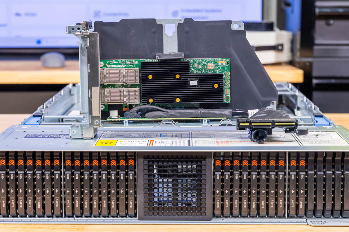
Removed Riser5 from Dell PowerEdge R770AP showing Broadcom-branded dual adapter boards and black heatsinks
Removed Riser5 from Dell PowerEdge R770AP, showing Broadcom-branded dual adapter boards and black heatsinks

This system uses 56G PAM4 SerDes networking, so we have 2x 200GbE ports here. We did not get to do it yet, but we are hoping to get these NICs tested through our Keysight IxNetwork XGS2 appliances.
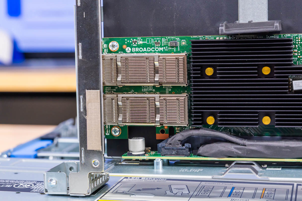
Closeup of Broadcom label, stacked adapter boards, port cages and heatsinks on Riser5 in Dell PowerEdge R770AP
Close-up of Broadcom label, stacked adapter boards, port cages and heatsinks on Riser5 in Dell PowerEdge R770AP

Here is a quick look at the riser’s connection and latching.
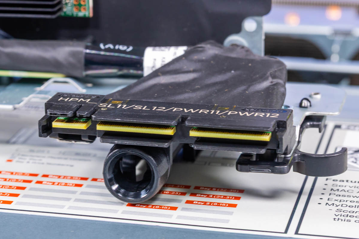
Underside view of Riser5 edge connectors labeled HPM/SL11/SL12/PWR11/PWR12 on Dell PowerEdge R770AP

Dell also has internal power headers to provide power to different components in the system. It is common these days to see cabled power to risers, NICs, and GPUs.
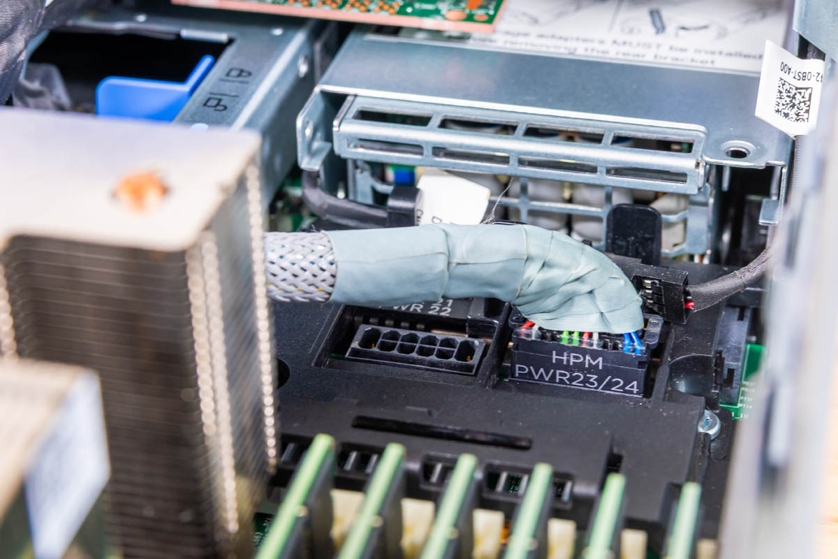
Rear internal power connection area next to CPU memory and riser in Dell PowerEdge R770AP with labels visible

This is the other side where you can see what the power connectors here look like.
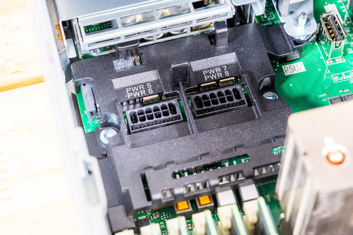
Rear internal connector block and PSL1 label beside PSU position in Dell PowerEdge R770AP

Amidst the internal PCIe Gen5 headers for the risers, we still found a USB port inside.
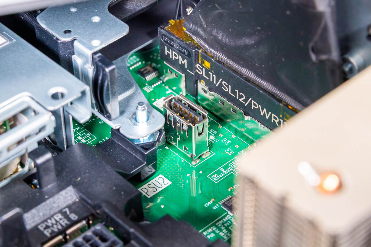
Rear internal mating board connectors with HPM/SL11/SL12/PWR11/PWR12 printed labels beside PSU in Dell PowerEdge R770AP

Here is a good look at the riser headers.
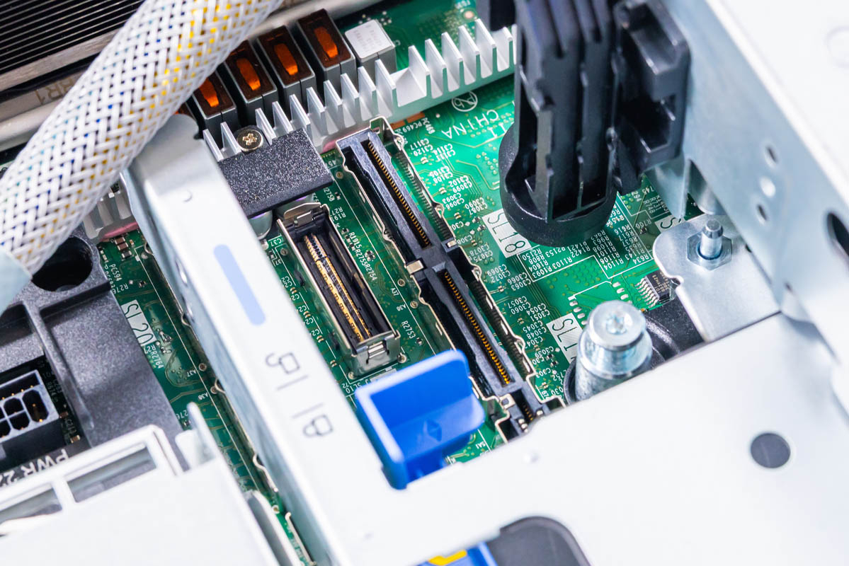
Rear system board closeup of card edge connector, blue latch and CPU_IO4 label on Dell PowerEdge R770AP

Here is another with the guide pins/ locks for the risers.
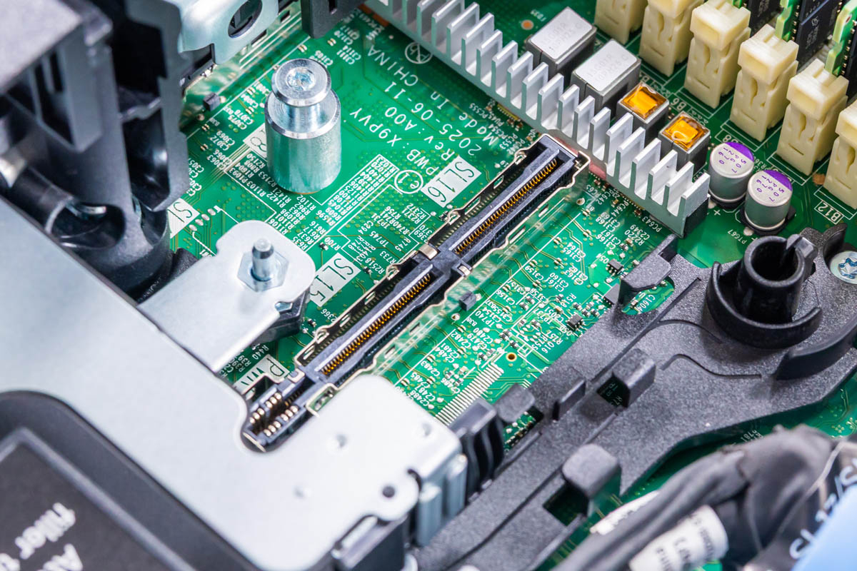
Second angle of rear system board slot with blue release tab after riser removal on Dell PowerEdge R770AP

Dell’s design team is keeping these slots close to the CPUs to help with the signaling as PCIe Gen5 has a very finite physical reach.
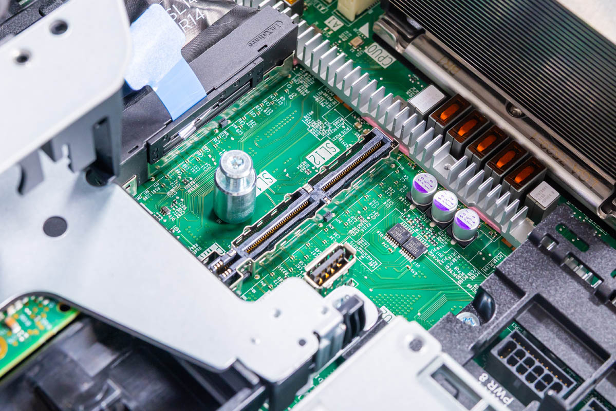
Adjacent rear board detail showing cabled connector and nearby card slot in Dell PowerEdge R770AP

Next, let us get to the topology.

LEAVE A REPLY

Please enter your comment!
Please enter your name here

This site uses Akismet to reduce spam. Learn how your comment data is processed.