
We have looked at many 2U 4-node servers in the past, but the ASUS RS520QA-E13-RS8U is a paradigm shift. So much that every time I have seen the server, it has been a prime target to review. We finally had the chance to get hands-on with the system earlier this year, and then run the server with some interesting results. This is not your standard 2U 4-node server since the nodes are single-socket AMD EPYC nodes, but memory is being added via CXL.
We filmed most of a video for this one in Taipei in January this year while visiting ASUS.
As always, we suggest opening this in its own browser, tab, or app for the best viewing experience. Since we had to travel and got special access, we need to say this is sponsored. Let us get to the hardware.
ASUS RS520QA-E13-RS8U Node Hardware Overview
We are going to start with the nodes, looking at one of the four of them. Then we will transition to looking at the chassis and the CXL setup next. The system has four nodes and is 900mm or 35.4in deep.
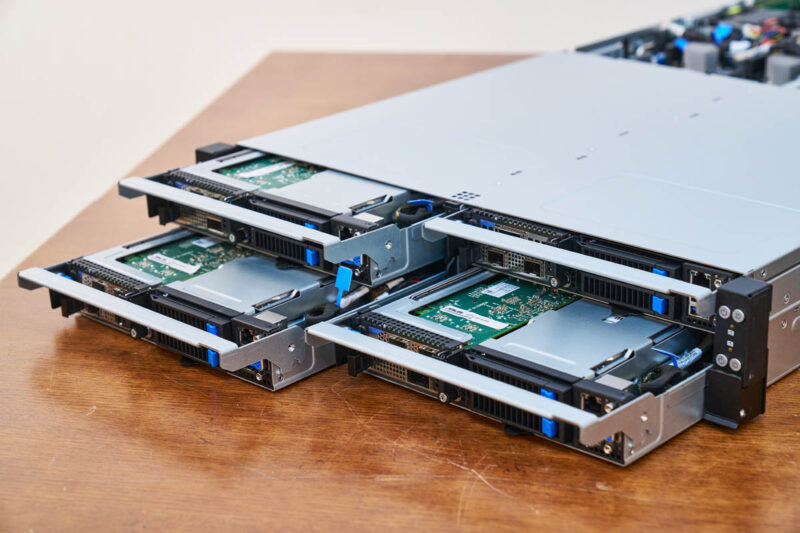
Pulling out a node, we can see that this is different. It is meant to be a front I/O node that can be replaced in the cold aisle. On the hot aisle side, only the power supplies are service items.
To make this happen, we need management, storage, and networking to be on the front side of each node.
All four nodes get the same setup, and because of the 2U 4-node configuration, it is easy to map drives to nodes. On systems where you have drives in the front and nodes in the back, it can be trickier to tie nodes to drives.
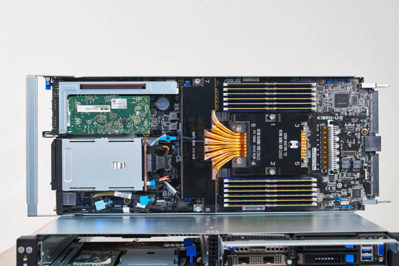
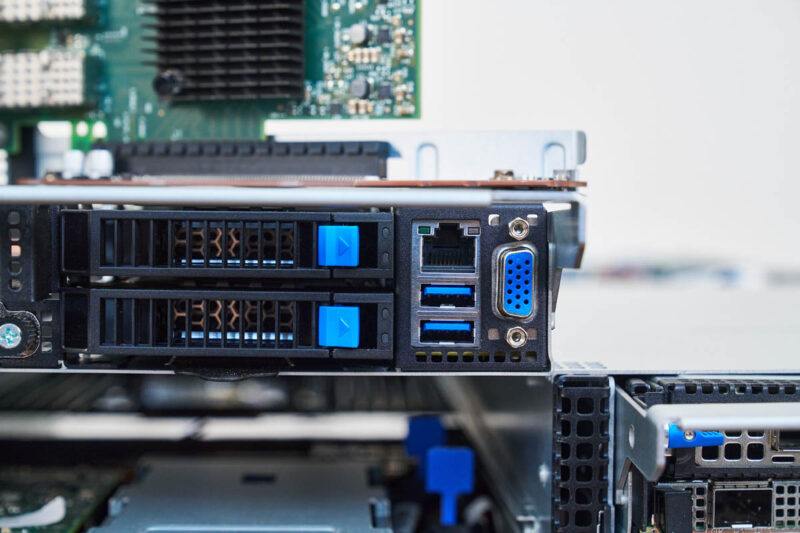
The system gets two 2.5″ NVMe SSD bays.
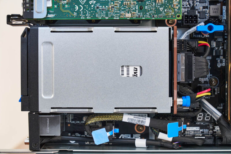
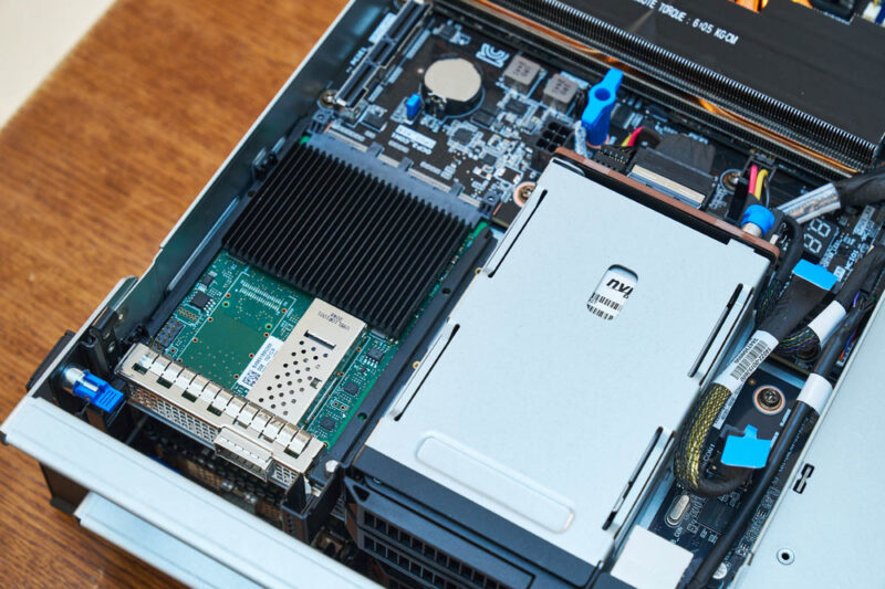
On the other side, we get our PCIe expansion for networking.
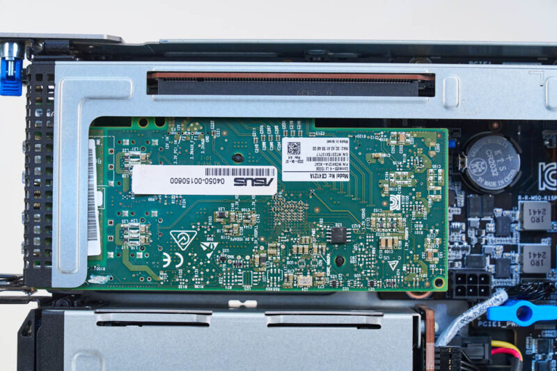
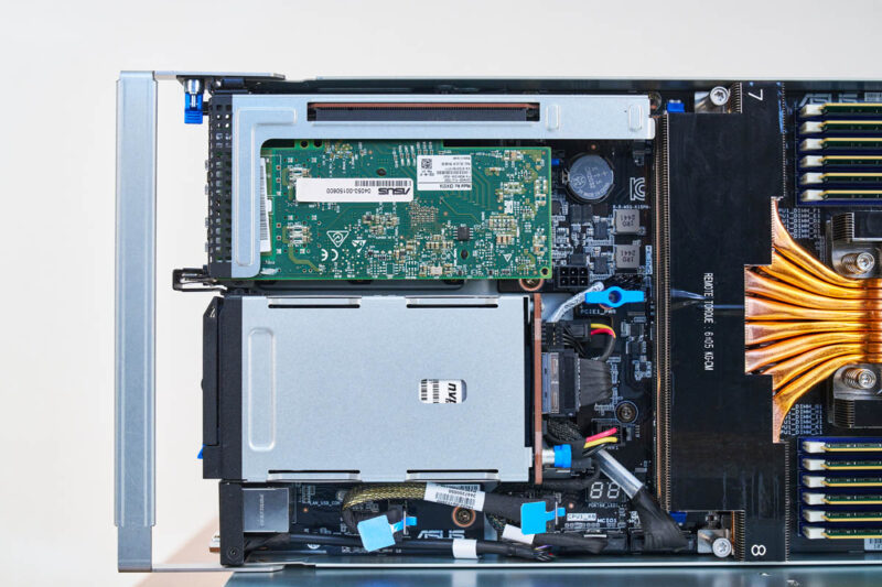
On top, we have a PCIe riser with a PCIe Gen5 x16 slot, but this can only fit low-profile expansion cards.
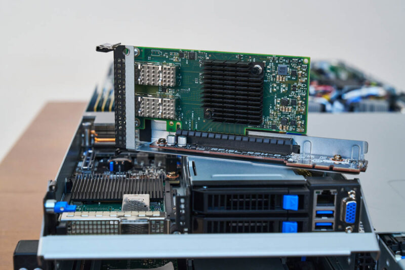
Underneath that riser, there is also an OCP NIC 3.0 slot.
Even as space-constrained as this system is, ASUS still has its POST code display on the motherboard.
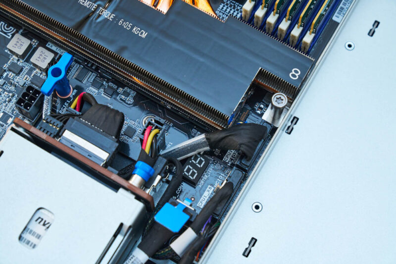
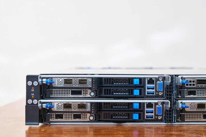
The final feature of the node is that we have the out-of-band management interface, two USB 3 ports, and a VGA port. This is so you can go down a cold aisle and hook up a KVM cart or access the system remotely via the management interface.
Behind the I/O and expansion, we get a massive heatsink that covers not just the CPU socket, but occupies the entire width of the node.
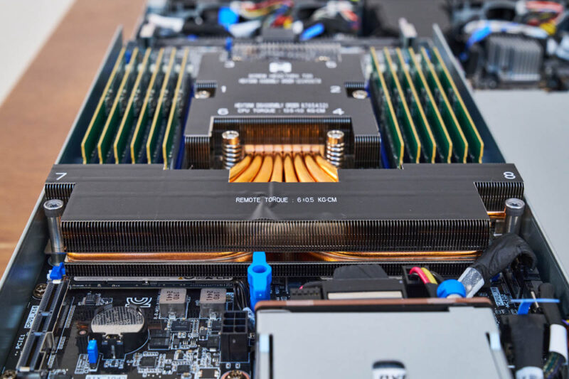
Eight heatpipes help to move heat away from the CPU socket. Still, this system is rated for up to 400W cTDP AMD EPYC 9005 “Turin” CPUs. This cooling and the SP5 socket are a big deal since one can get up to 192 cores in a system like this. Instead of requiring two CPUs that are in series, with the second CPU getting pre-heated air from the first, the single socket design with AMD EPYC 9005 means we can get more density than previous generation Xeon dual-socket systems but using a single socket node.
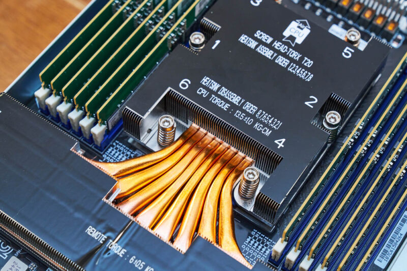
Next to the AMD EPYC 9005 CPU are twelve DDR5 DIMM channels. This is a key feature that we talk about a lot in the video and in the CXL discussion. You can easily see the challenge here. The twelve memory channels and CPU socket fill the width of the half-width node. As a result, doing 2DPC and having 24 DIMM slots, while possible for the CPU, is physically impossible here. Instead, that capacity comes from the CXL expansion.
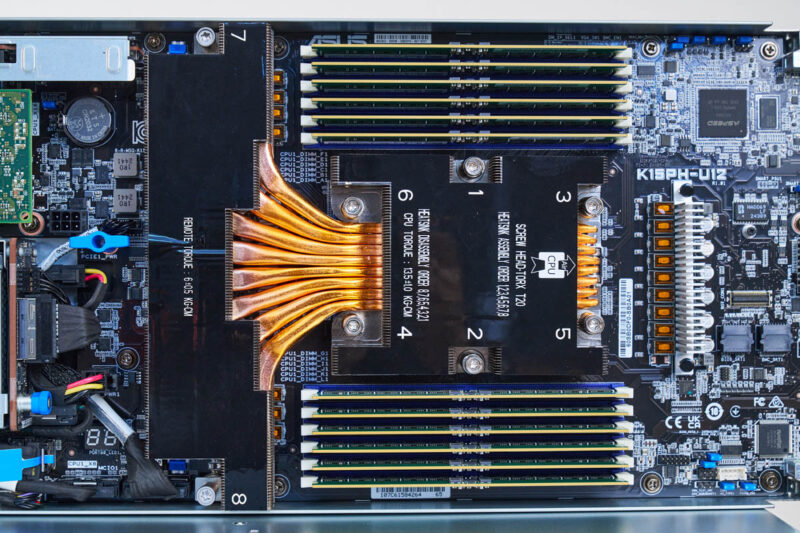
Behind the CPU, we have guide pins and connectors for power and data.
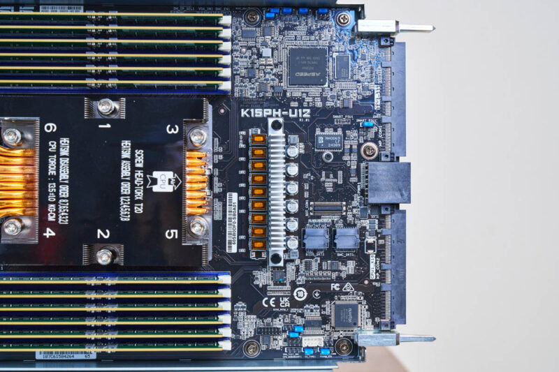
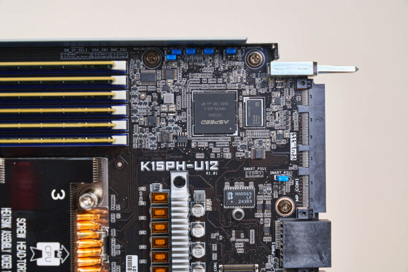
We also have the ASPEED AST2600 BMC.
Of course, the neat part of this server is not just the single-socket node, but it is the CXL behind that node which we will get to next.


It’s nice, but I much prefer CXL memory expansion to be sharable between all the CPUs in a box instead of being a much simpler expansion, where a block of memory (8 DIMMs per node times 4) is not fully shared (32 DIMMs splittable (dynamically allocated) between 4 nodes). Examples in STH articles: “Lenovo Has a CXL Memory Monster with 128x 128GB DDR5 DIMMs” and “Inventec 96 DIMM CXL Expansion Box at OCP Summit 2024 for TBs of Memory”.
what kind of application need so much memory but very few storage & PCIe extension ?
Comments are closed.