ASUS RS520QA-E13-RS8U Chassis and CXL Hardware Overview
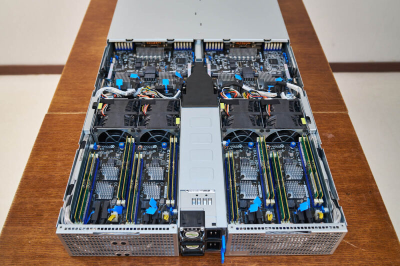
Just for orientation, this is the chassis looking front to back.
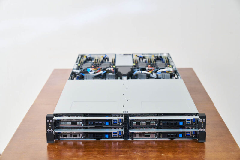
The nodes are inserted at the front, leaving a lot of area in the 900mm depth chassis.
Looking at the rear of the chassis does not offer that much help. The only things we see here are the power supplies.
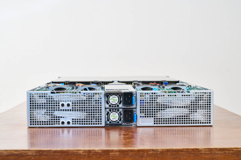
There are redundant Delta power supplies, but otherwise, the rear has very little.
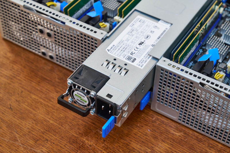
Next to the power supplies, in the rear, however, is the cooling and CXL setup.
This starts with the connection board for each node. In the center we have power, and on the sides, we have data connections. We asked and were told under these two heatsinks are PCIe/ CXL retimers.
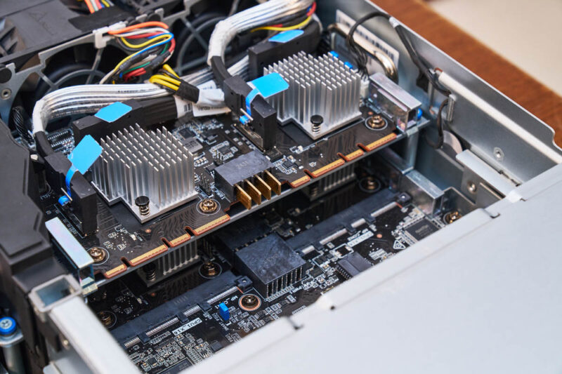
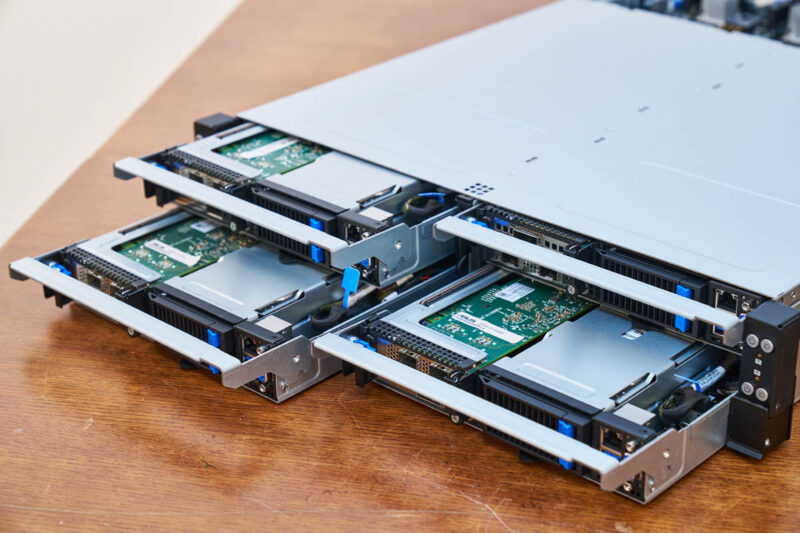
Here is a look at the connections being made between the node and the retimer board. One might note that the connectors look a lot like OCP connectors.
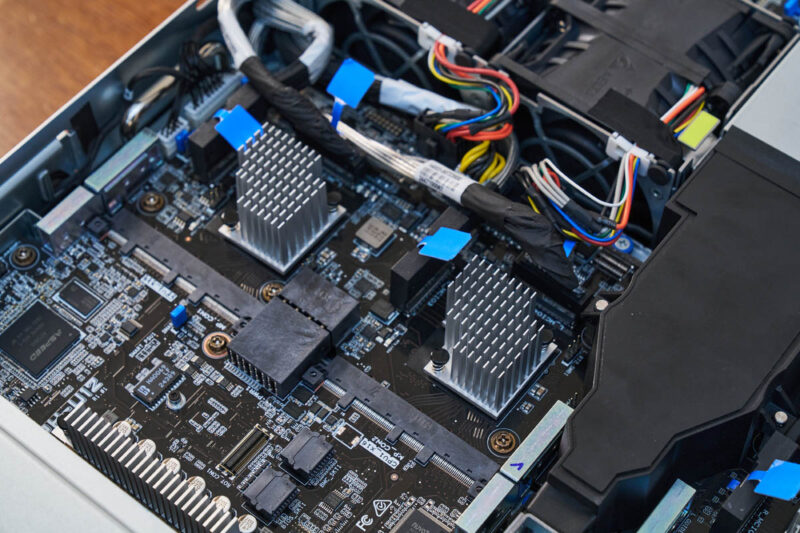
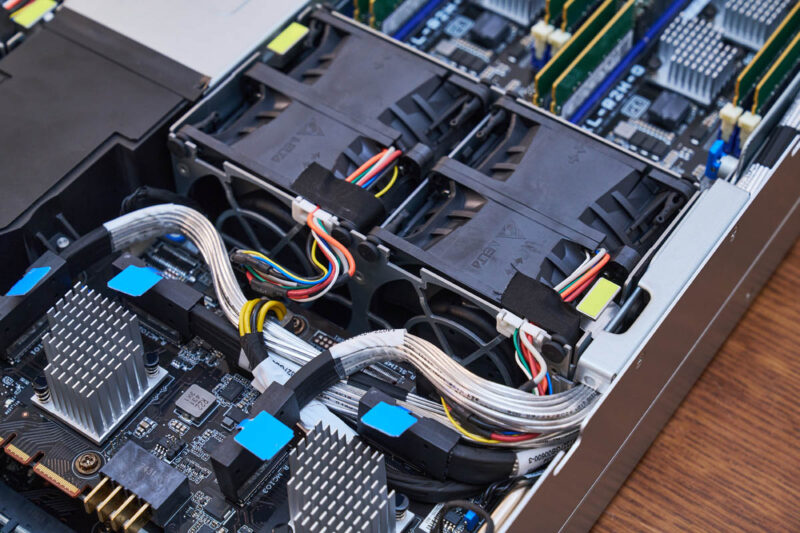
The reason those retimer boards are important is because after crossing the node PCB, the connectors, and the retimer PCB, the retimed signal goes through cables to the CXL boards. These cables allow the signal to get around the fans that cool the components.
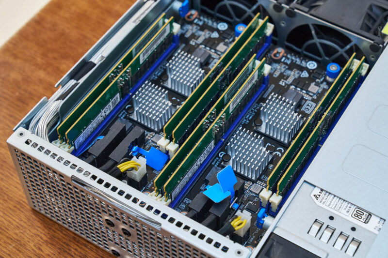
The CXL-R2H-Q boards connect via those cables and also have power inputs.
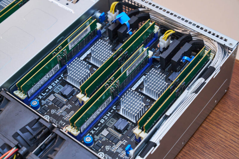
On each, and there are two per node, there are two Montage CXL memory controllers and four DDR5 DIMM slots. Each node can expand the twelve DDR5 DIMMs on the main node motherboard with another eight DDR5 DIMMs. If you recall, the nodes do not have room to fit 20x DDR5 DIMM slots across the half-width nodes. This setup allows for up to 20 DDR5 DIMMs to be used per CPU while also retaining the 4-nodes in 2U design.
At this point, you might be wondering how this works, so let us get to that next.


It’s nice, but I much prefer CXL memory expansion to be sharable between all the CPUs in a box instead of being a much simpler expansion, where a block of memory (8 DIMMs per node times 4) is not fully shared (32 DIMMs splittable (dynamically allocated) between 4 nodes). Examples in STH articles: “Lenovo Has a CXL Memory Monster with 128x 128GB DDR5 DIMMs” and “Inventec 96 DIMM CXL Expansion Box at OCP Summit 2024 for TBs of Memory”.
what kind of application need so much memory but very few storage & PCIe extension ?
Comments are closed.