Cisco Catalyst C1300-16XTS Internal Hardware Overview
With the cover removed, the internal layout is easy to understand. Power supply, cooling, and main switch board placement are separated cleanly. That is what we want to see in a switch expected to handle a lot of 10GbE traffic and stay online for long periods.
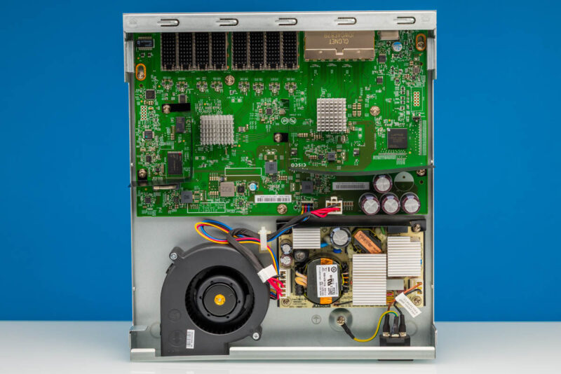
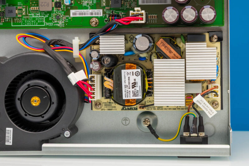
Inside, the power supply occupies its own area of the chassis. Using an internal supply keeps the installation cleaner than an external brick and better aligns with the more business-focused nature of this switch. It is another point where this feels different from the lowest-cost 10GbE switches we have reviewed.
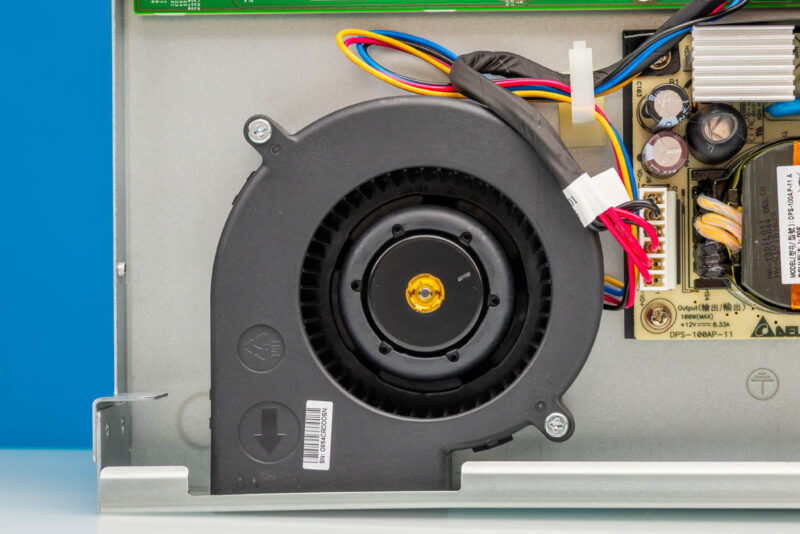
Cooling is handled by an internal fan. That is expected for a managed 10GbE switch with this many copper ports, since 10Gbase-T PHYs and the switch silicon need steady airflow. As with other C1300 units we have reviewed, this has a blower fan which is quite different from the normal 40mm fans we see in a lot of switches in this class.
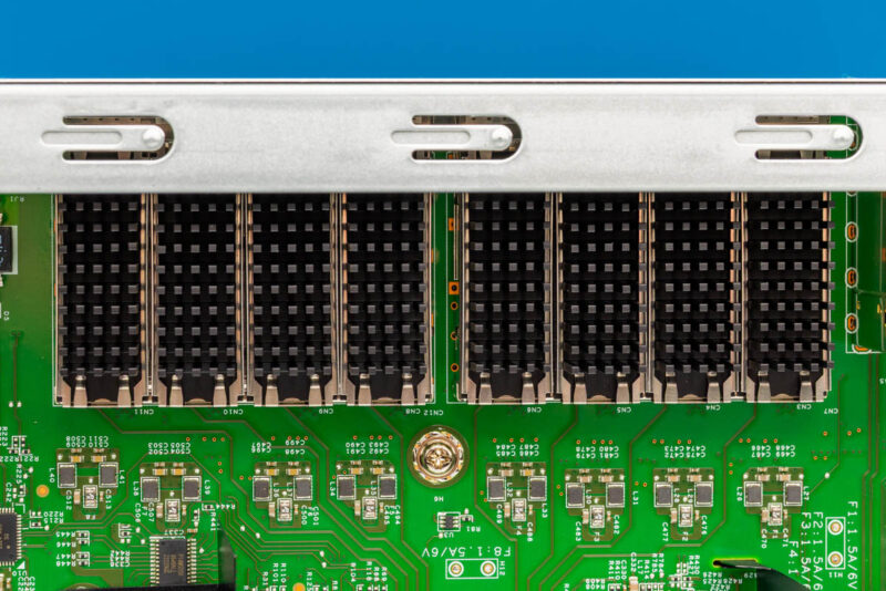
From the inside, we can also see the SFP+ port area. These have small heatsinks, which are more common on higher-speed ports. At the same time, this is just a small quality step that helps differentiate Cisco’s design from the many others with bare SFP+ cages.
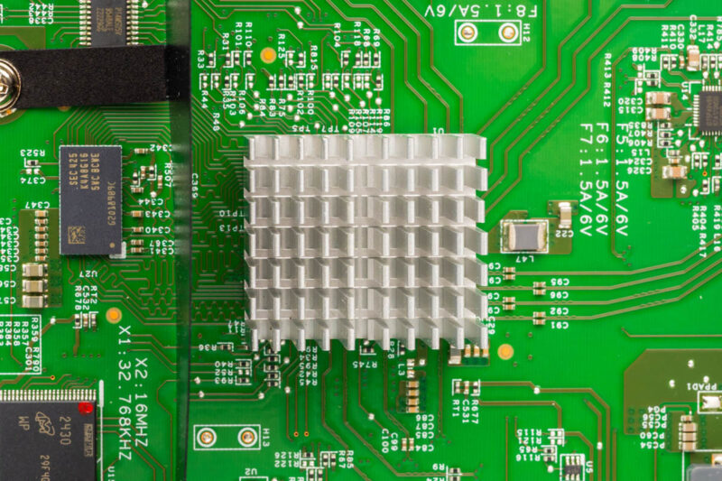
A large heatsink covers the main switch silicon and PHYs. The heatsinks were affixed, so we did not take them off.
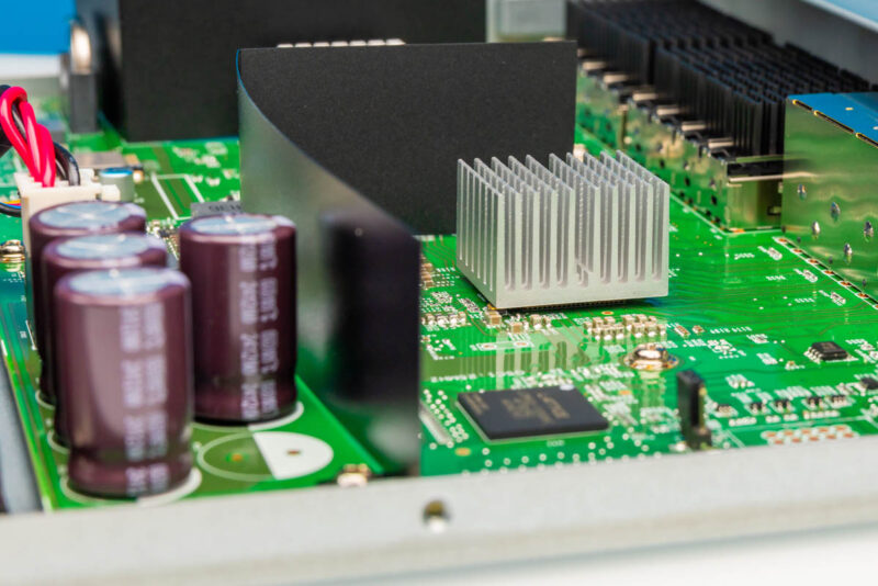
A wider internal view helps show the relationship between the board, heatsinks, power supply, and fan. Another notable bit here is that the switch has internal airflow guides, again showing the attention to detail.
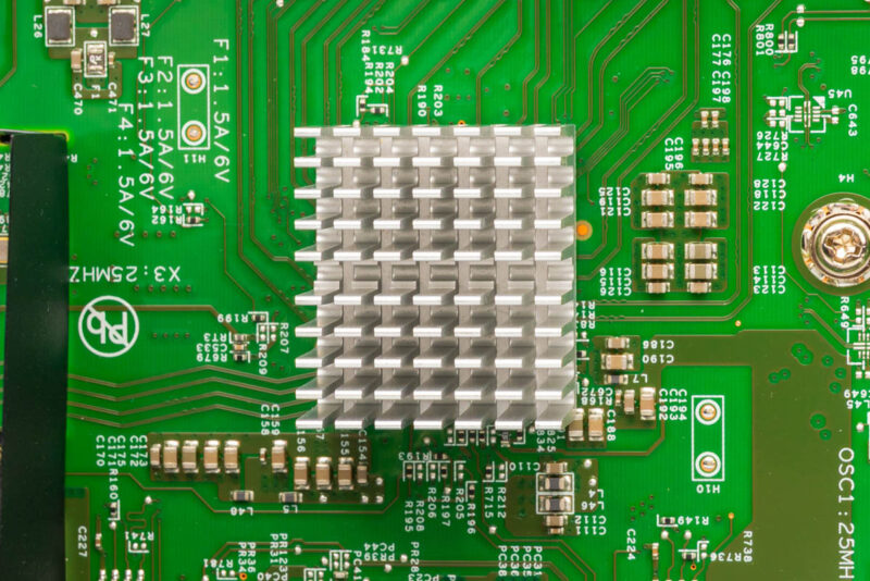
Here is the second heatsink. Which is again fixed. Our best guess is that Cisco is using Marvell’s chips like the other C1300’s we have seen.
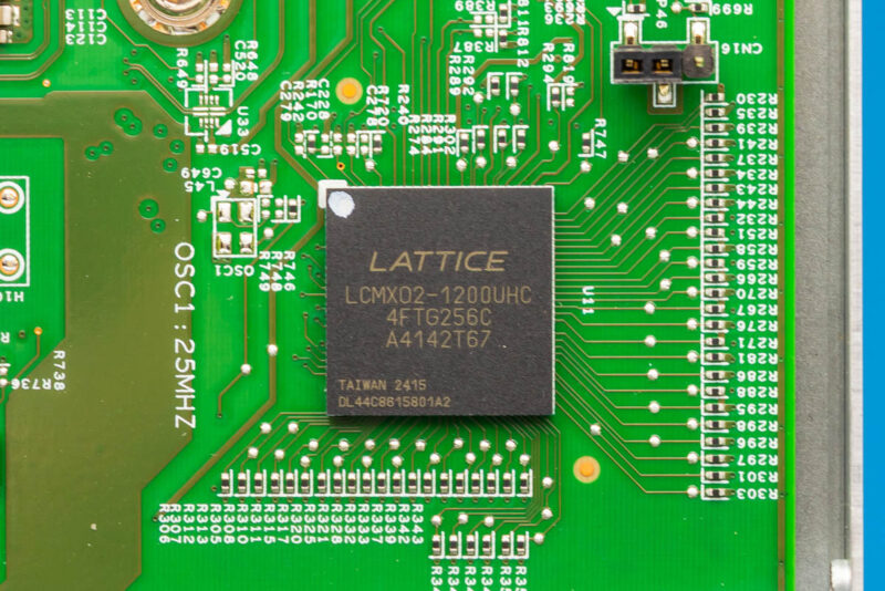
One of the visible logic devices is a Lattice LCMXO2 part. We often see programmable logic used for board-level control tasks in networking hardware. It is still useful to note because it shows this is a more complex platform than a very low-cost unmanaged switch.
Next, let us get to management.


Any chance we could get a confirmation on the 10G-BaseT Copper ports supporting 2.5g/5g? Also I didn’t see any noise numbers in the review?
Cheap?! The switch is over 2k new…FYI you never mentioned the price or the noise levels.
@Switch Gears: Where in the article did they say it was cheap? They kept talking about how expensive it is. The price was in the Amazon link in the second paragraph.
Finally a company who designed a switch for the future.
we all are evolving from UTP to SFP+, but still the need POE , which is missing on the UTP ports.
So we still have to split the between a SFP+ and a separate UTP POE+ switch to cover all your needs. also price wise
Why is it sooo difficult to make a switch covering all needs in ONE.
SFP+ plus Min 8 UTP POE(+) Ports for $500
Cisco, a POE version of this, please. Please please olease
If you change the drop down in the gui from basic to advanced you’ll get to see more configuration options.
This is supposed to have (some) L3 functionality. Can you not test that, routing etc?