
Bread, meet butter. The Gigabyte R181-2A0 is perhaps that simple in its concept. This is a mainstream 1U dual-socket first and second-generation Intel Xeon Scalable processor server. When we look to the R181-2A0 we see the company’s offering for high-levels of 1U expandability with a standard 10-bay 2.5″ storage array in front. In our review, we are going to take a look at a mainstream Gigabyte 1U server offering.
Gigabyte R181-2A0 Overview
The R181-2A0 is a fairly standard 1U server form factor. There are a total of 10x 2.5″ bays across the front of the chassis. All ten of the drive bays are wired for SATA which we expect will be the most common configuration. These bays can be used for SAS but they require a SAS controller to do so. For those who are interested in NVMe options, Gigabyte has variants of the R181 platform with 2-10 NVMe SSD bays.
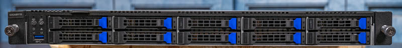
One can also see status LEDs and power buttons. There is even a USB 3.0 front panel port which is not on all server models.
The rear of the chassis is a fairly typical layout. There are two redundant 1.2kW 80Plus Platinum PSUs on the left.
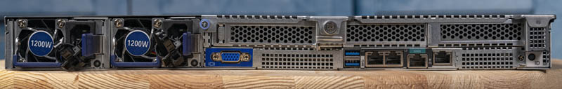
Expansion slots are the primary focus even given the constrained 1U form factor. We see three low-profile expansion slots along the top row. Two are PCIe Gen3 x8 and one is a PCIe Gen3 x16 slot. The bottom row has cutouts for two OCP NIC 2.0 form factor slots.
Looking at the rear, one can see a VGA port near the power supplies. The remainder of the I/O block is on the other side of one of the OCP NIC slots.
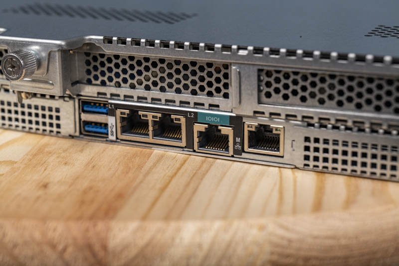
On the main rear I/O block we can see two USB 3.0 ports, two 1GbE network ports, a serial console port, and an out of band management network port. The two 1GbE ports are based on a nice Intel i350-am2 NIC, a higher-end option versus using two i210 controllers. Flanked by two OCP NIC slots, these are designed for lower-performance uses such as OS and hypervisor management interfaces while higher-speed NICs are installed and used for primary networking.
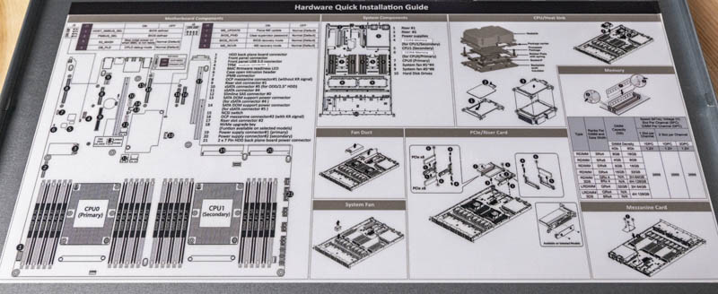
Opening the top lid, one can see that Gigabyte has a nice hardware installation guide. This is more similar to what one would expect to see in a traditional large OEM system, such as a Dell EMC PowerEdge, HPE ProLiant, or Lenovo server. Many white-box vendors do not utilize these nice service guides. This is a good example of how Gigabyte’s servers are much more mature than they were generations ago. These hardware installation guides help remote hands perform field service even if they may not have worked in the server previously.
Inside the chassis, we see a fairly standard 1U server layout. Drive bays are to the left of the below. Working to our right we see fans, the CPU and memory, and finally the I/O, PCIe, and power supplies.
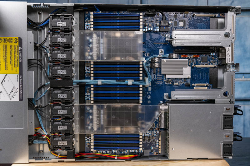
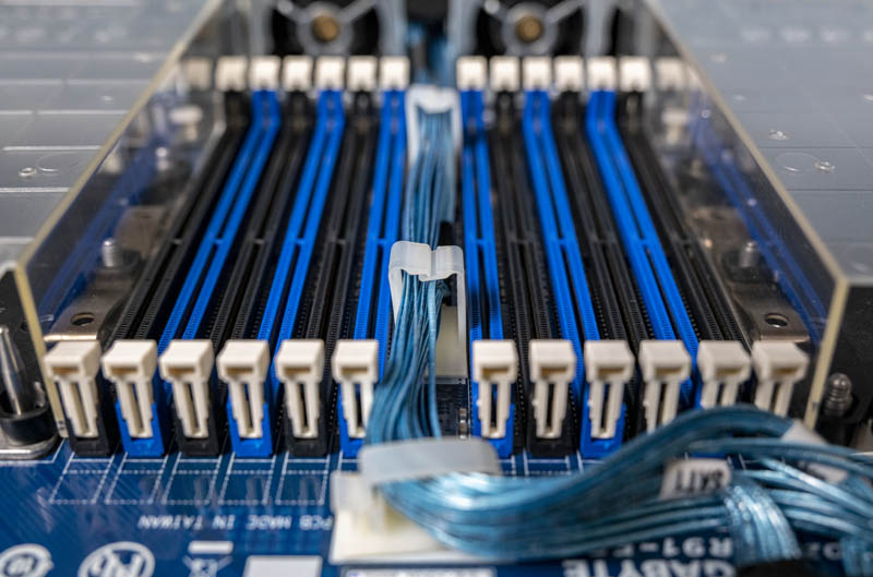
The biggest feature to the G181-2A0 is the LGA3647 Socket P setup. Note these are Socket P not P+. These are sockets capable of handling 205W TDP CPUs for the 1st and 2nd Generation Intel Xeon Scalable line along with a full set of 12 DIMMs per CPU (24 total.) The system even supports Optane DCPMM. This gives the R181-2A0 the ability to handle all of the 2nd Gen Intel Xeon Scalable Refresh SKUs along with all of the previous Xeon Scalable processors and Optane memory. Not all 1U servers can handle the higher-end 205W TDP CPUs and high-end DCPMMs.
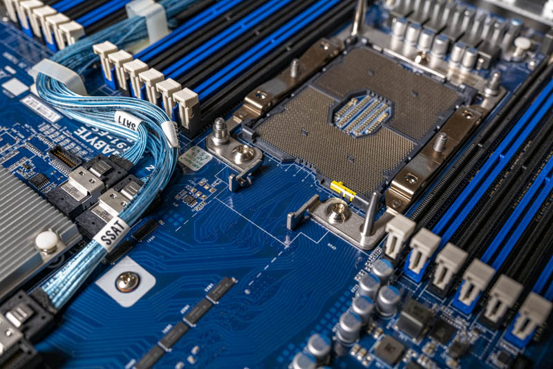
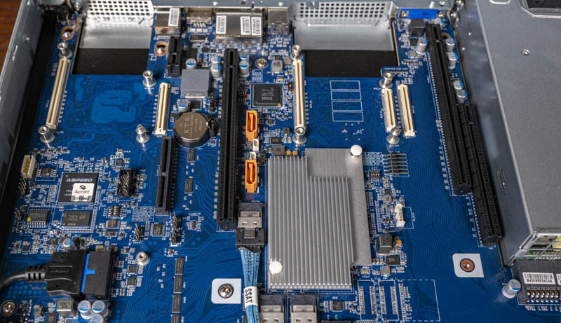
Going through the photos, this shot gave me pause. It shows some of the thinking behind the original LGA3647 socket and how flexible it was designed to be. For example, this socket is the higher-end version which has the retention mechanism for Intel’s Omni-Path “F” SKUs although Intel stopped releasing SKUs with integrated OPA after one generation. Also, that small yellow key shows how expansive Intel was thinking with the Xeon Scalable design. These are very small features, but ones we can see on the higher-end sockets today.
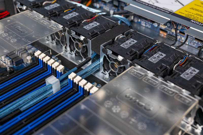
The fan array is extensive. There are eight Delta fan modules each consisting of two fans. This is a design for reliability and redundancy in the 1U form factor. While the fans are not the easy-to-swap modules we see in 2U and larger servers, in the 1U form factor this is very common due to space constraints. The wires terminate at the storage backplane which makes them significantly easier to service than if Gigabyte had used motherboard fan headers. This is a small detail, but it is a nice refinement from previous generations.
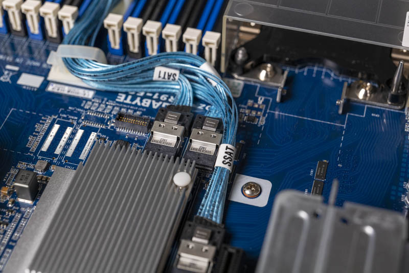
The ten front panel bays are connected via three cables. Gigabyte even labels the cables so one can see which set is controlled by the sSATA portion in the system’s BIOS.
Another small but welcome refinement is the cable retention solutions that we see. In previous generations, cables would be simply placed between DIMM sets. There is now a cable management solution that keeps the cables in place. If you have ever serviced a server and had a cable migrate in the path of a DIMM installation, this small change is a welcome one.
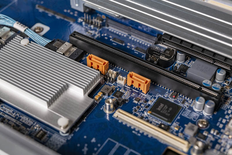
Rounding out the SATA capabilities are two “gold” SATA ports. These support SATA DOMs and specifically they can power SATA DOMs without an external cable. If your DOM solution still requires a cable, there are two power connectors next to the ports.
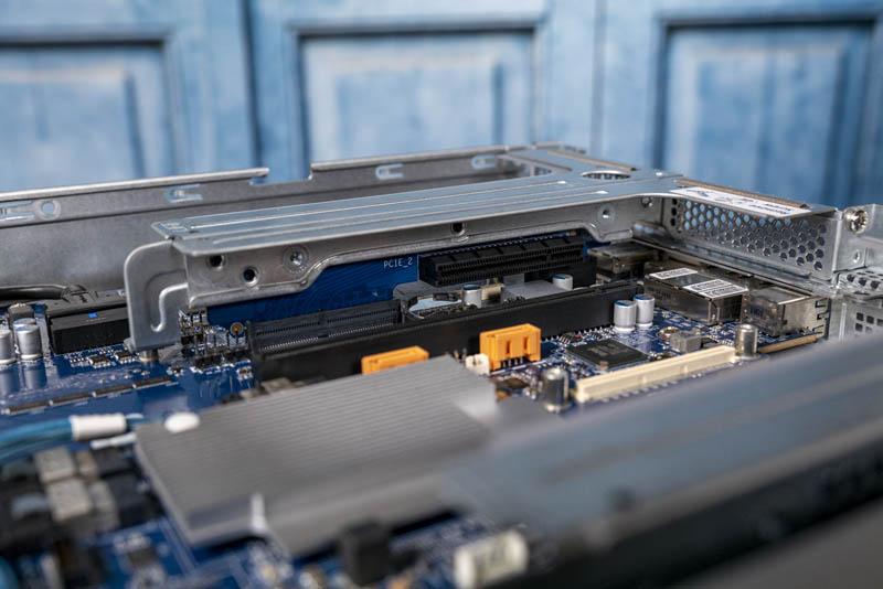
The PICe expansion is provided via a series of risers. There are two PCIe Gen3 x8 slots along with a PCIe Gen3 x16 slot.
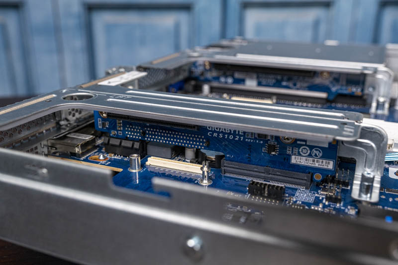
One can see that below the risers there are additional riser slots. Gigabyte uses a common motherboard to support 1U configurations such as this, along with larger solutions such as 2U servers. Keeping the motherboard standardized helps reduce costs and increase quality through increased volumes. It also makes servicing 1U and 2U Gigabyte servers easier in clusters since they have familiar layouts.
Taking a quick look underneath the risers, one can see the two OCP NIC 2.0 slots (white) that are often used for higher-speed networking. OCP NIC 2.0 was popular, but the next-generation OCP NIC 3.0 will be the defacto industry standard in future generations.
Something we did not find in this server was M.2 slots. M.2 has become fairly common for boot and cache SSDs. Gigabyte seems focused on providing flexible connectivity via traditional SATA, PCIe, and OCP slots rather than routing signals to M.2 slots. This is just something to be aware of when configuring the servers.
Next, we are going to look at the topology before getting to management and performance.


I would LOVE to see the whitebox OEM version of the hardware setup guide that is pasted inside this chassis.
The mis-spellings, sentence structure & syntax, and translation (from whatever to English) errors could be hillarious reading!
Sleepy, your mistaken here. HPe take these systems and market them as their own. The quality and translation is brilliant
Comments are closed.