
The ASRock Rack ROME2D16-2T is a big motherboard that packs many great features. While many of the modern server designs utilize custom PCBs to allow maximum utilization of a 1U or 2U chassis, there is still a significant market for motherboards that can fit in a wide variety of cases for even more customization to an application. Packing dual AMD EPYC CPUs and a lot of expansion into an EEB motherboard in a well-executed manner is not a simple task, so in our review, we are going to see how ASRock Rack designed this platform.
ASRock Rack ROME2D16-2T Overview
The motherboard itself is a larger SSI EEB form factor that is 12×13″ or 305x330mm. Some may want smaller motherboards, and we have looked at the ROMED4ID-2T, the ROMED6U-2L2T, and the ROMED8-2T for smaller AMD EPYC form factors, but this is designed to be a solid dual-socket platform.
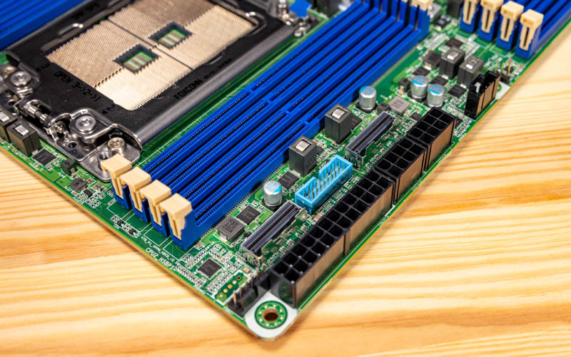
The main feature of this system is probably that it is a dual AMD EPYC system. We tested using the AMD EPYC 7002 “Rome” and EPYC 7003 “Milan” series CPUs since this is a PCIe Gen4 platform. Each CPU gets eight DDR4 slots. These DDR4 memory slots fill all eight memory channels of the EPYC processors. With 16 DIMMs total, we get support for up to 4TB of memory on this platform.
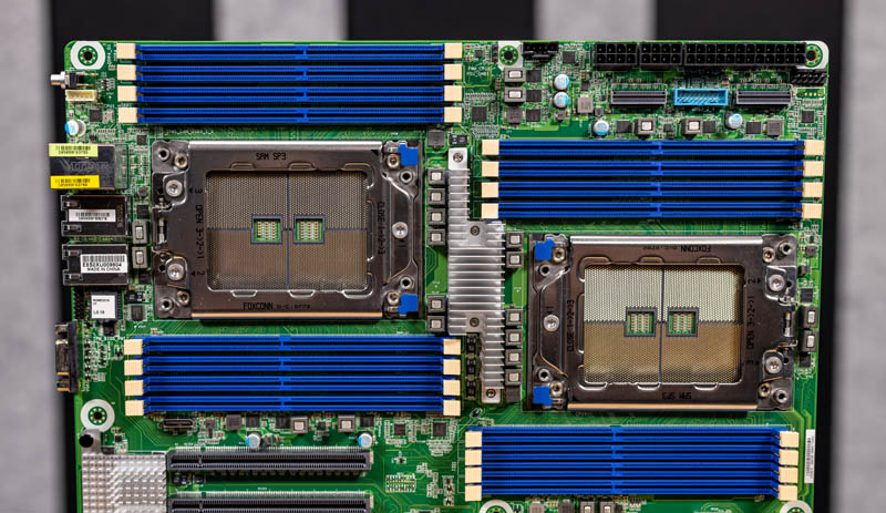
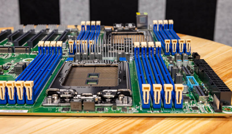
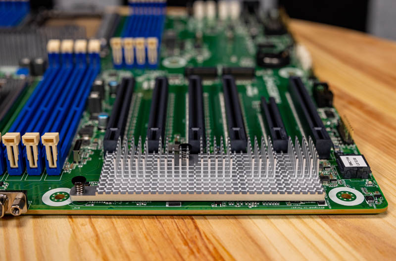
Something else we wanted to quickly note is the airflow. In these “channel” form factor boards, instead of proprietary form factors, we often have the CPU sockets and memory slots at the top of the motherboard in an aligned or slightly offset series. We can see here that this is an offset series of sockets. Offset is generally preferred since it allows for better cooling of the second CPU socket, but it also means that the DIMM slots will interfere with larger PCIe cards in some of the PCIe slots. There are trade-offs everywhere. Also, for our readers that want to use larger consumer-style coolers, those coolers are often oriented for bottom to top airflow instead of front to rear.
In terms of PCIe, we get six PCIe slots. Five a PCIe Gen4 x16 slots. One is a PCIe Gen4 x8 slot. One can see that the top x16 slot does not have the same depth as the others due to the DIMM slot placement from the offset CPU sockets. That means, for example, that you are unlikely to put a large GPU in this slot.
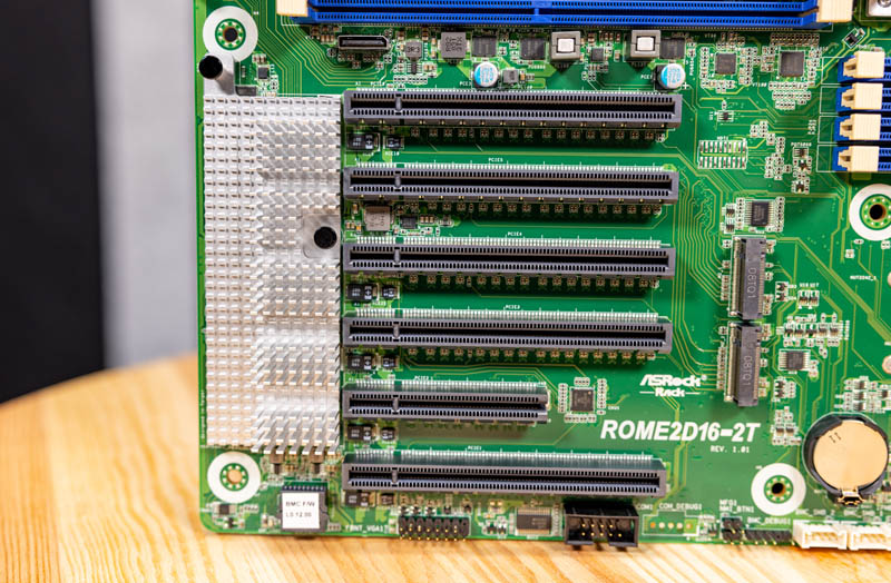
Behind these PCIe slots, we have two M.2 slots with 42mm, 80mm, and 110mm (M.2 2242, 2280, 22110) mounting options. If you want redundant boot devices, cache drives, or something similar, then this is a great option. We will quickly note that this mounting position can be a challenge if one uses a large heatsink on a M.2 SSD here in conjunction with a large PCIe card such as a GPU.
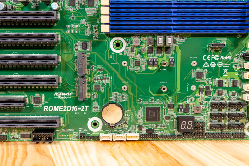
Along the bottom of the motherboard, we have a ton of headers for various features such as TPMs. We also get a Dr. Debug display for POST codes that is very useful when debugging a system.
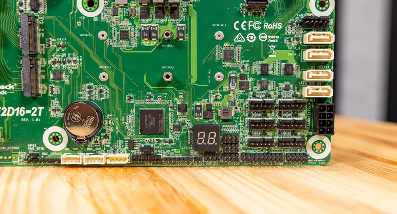
The bottom corner of the motherboard has six of the eight 6-pin fan headers (these can be used with 4-pin fans as well.) Airflow on a system like this will be a big deal, so it is nice to see this block. Next to those fan headers, we can see a PCIe power input if you are going to use many PCIe devices (e.g. over 12A of current.) Finally, there are four standard 7-pin SATA ports with the 7th 6-pin fan connector above them.
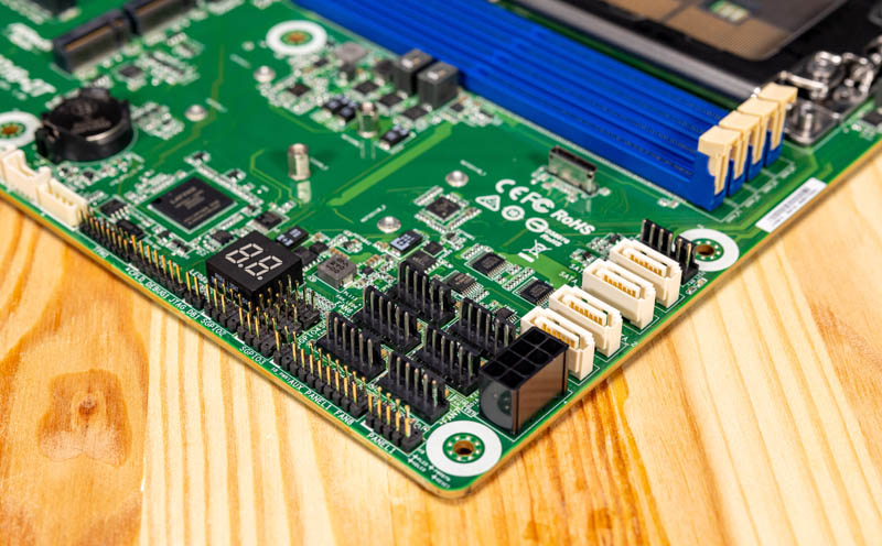
We are going to address the SlimSAS connectors in the next section, along with Oculink, but along the top of the motherboard, we get a few important features as well. We get the power inputs as well as the USB 3 front panel header. We can also see the eighth 6-pin fan connector flanking the top corner mounting hole along with the ATX power connector.
The rear I/O in this system consists of an out-of-band management port above two USB 3 ports. There are two NIC ports for 10Gbase-T networking, a nice upgrade over 1GbE. Finally, there is a VGA port.
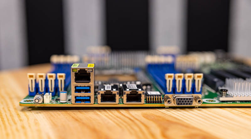
One quick note on the above photo. One can see on the left side that the top left mounting hole for this motherboard is in the far corner. Many chassis will require a stand-off to be removed in order to accommodate this. SSI EEB has an option here and many cases also have a standoff for ATX boards so this is just something to keep in mind. ASRock Rack needed to place the mounting point here because of the DIMM slot placement.
We get a nice heatsink between the edge of the motherboard and the PCIe slots. This is for cooling the X550 NIC powering the 10Gbase-T ports as well as the ASPEED AST2500 BMC.
Overall, this is a feature-packed solution, but you may be left wondering what about if you want more SATA connectivity or to connect more NVMe SSDs. ASRock Rack has some additional functionality we are going to focus on in the next section on SlimSAS and Oculink.


Did I understand that this motherboard uses the infinity fabric interconnects between sockets which since others use for interconnects? If so, is there a way of measuring the performance difference between such systems?
Yikes, my question was made difficult to understand by the gesture typing typos. Here’s another go at it:
Did I understand that this motherboard uses three infinity fabric interconnects between sockets which since others use four interconnects? If so, is there a way of measuring the performance difference between such systems?
This will be really a corner case to measure. You need to have a workload that needs to traverse these links consistently in order to see any difference.
Something like GPU or bunch of NVMe disks connected to the other CPU socket.
If you consider how many PCIe lanes are in these interconnects you will notice that the amount of data that needs to be pushed through is really astounding.
Anyway if you want to see the differences you may want too look up the Dell R7525
There might be a chance that they tested it in the spec.org in the without xGMI config (aka 3 IF links). You may then compare it with HPE or Lenovo which are using NVMe switches.
I am looking to purchase the ROME2D16-2T Qty30
What is the ETA and price ?
Can diliver this ROME2D16-2T for a very sharp price from The Netherlands.
Hello Patrick , I am trying to find the specs of the power supply you used in your test bed for this MB ?
Tia , JimL
How are the VRM temps? I can get this board and 7702 EPYCs for a good price however those phases look really basic well… like all the epyc boards. I don’t want to run some exotic water cooling or something, jet engine fans.
I can only get 1x slimsas port working is it shared with something else ? 2P installed
only 1 shows in bios , now thinking I should have gone the OCuLink path as they both show
also anyone found what powered usb3 hubs work with this , every thing I have tried fails
tried a dozen internal usb3 cards all fail
unpowered USB2 Hub with built in audio works but keeps crashing the USB Chip
Comments are closed.