Gigabyte H262-ZL0 CoolIT Liquid Cooled Node Overview
We have reviewed a number of 2U 4-node Gigabyte servers previously, so we are going to mainly focus on the liquid-cooled aspects of the Gigabyte H262-ZL0.
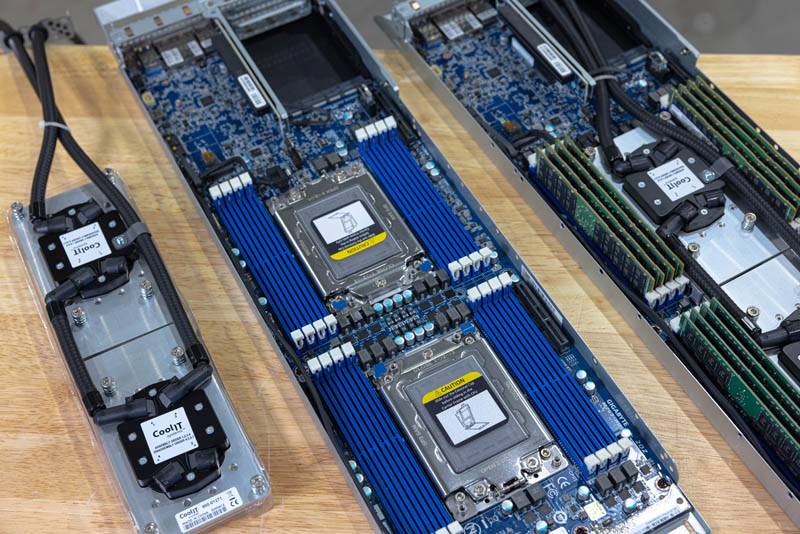
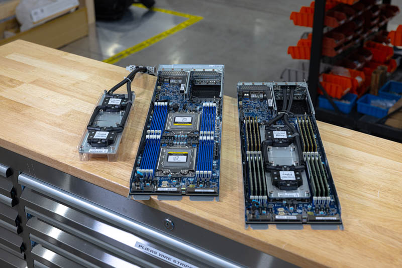
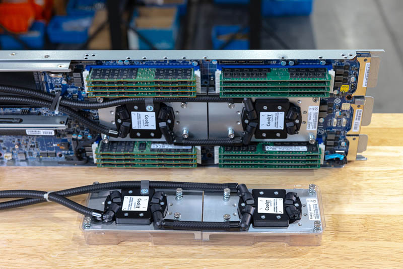
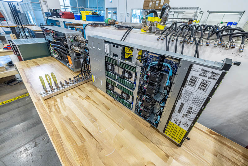
Just for some terminology, the PCL stands for Passive Coldplate Loop. This is the two water blocks with tubes attached on the right of these images. The PCL is specifically designed to fit in the Gigabyte H262-ZL0 node that is shown without components in the middle. On the right, we have a fully completed node. I built all four nodes in the lab and luckily they all worked.
Something that I noticed is that the tubes between the water blocks need to be exactly the right size so that they cool the CPUs along with the VRMs on the motherboard. If they were too short, things would not align. If they were too long they would interfere with the DIMMs or the chassis/ node above.
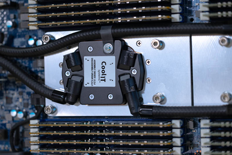
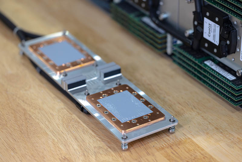
Here is a look at the cooling assembly for one of the CPUs.
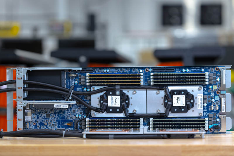
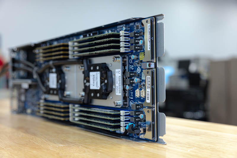
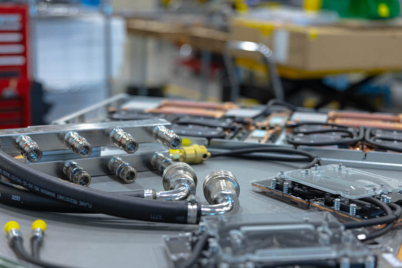
This is a gratuitous photo that I just liked so we are using it here. Credit goes to Steve for capturing this one.

Since we cannot show the installation in photos as easily as videos, hopefully this view of the PCL on the workbench next to the completed node will help our readers understand how this fits together.
Thermal paste is pre-applied to the PCL both for the CPU as well as the VRMs.
Here is a view of the motherboard connectors that connect the node to the H262 chassis that we showed on the previous page.
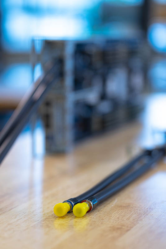
Once the PCLs are installed, they need to get cool liquid into the CPU blocks and then expel the hot liquid from the node. To accomplish this, tubes attach to the rear of the node just above the OCP NIC 3.0 slot. Adding these tubes means that we lose the riser above the OCP NIC slot that we see on some systems because the space is being used for tubing.
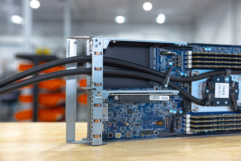
The tubes have rubber grommets to ensure that they can safely reside going through a metal I/O plate that installs in the low profile expansion slot.
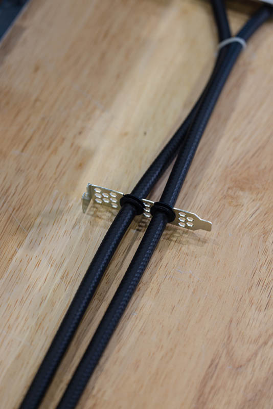
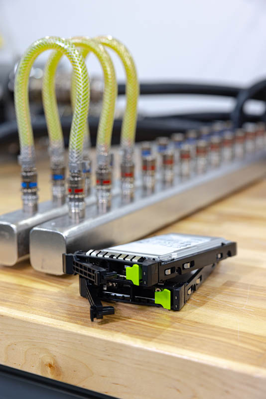
Here we have the Staubli hot and cold quick disconnects that attach to the rack manifold. Blue means “Cool” or “Cold” and red means “warm” or “hot”. Hopefully this is intuitive for many of our readers, but we will see why these dripless quick connectors are important as we build up the solution.
There is still a PCIe Gen4 x16 low profile slot in addition to the OCP NIC 3.0 slot. We also have an internal M.2 slot for a boot SSD if the front 2.5″ bays are not enough.
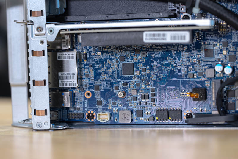
On the rear of the unit, we have a management port, two 1GbE ports, two USB ports, and a miniDP for video output. There is no room for a VGA port on this system so miniDP is used instead.

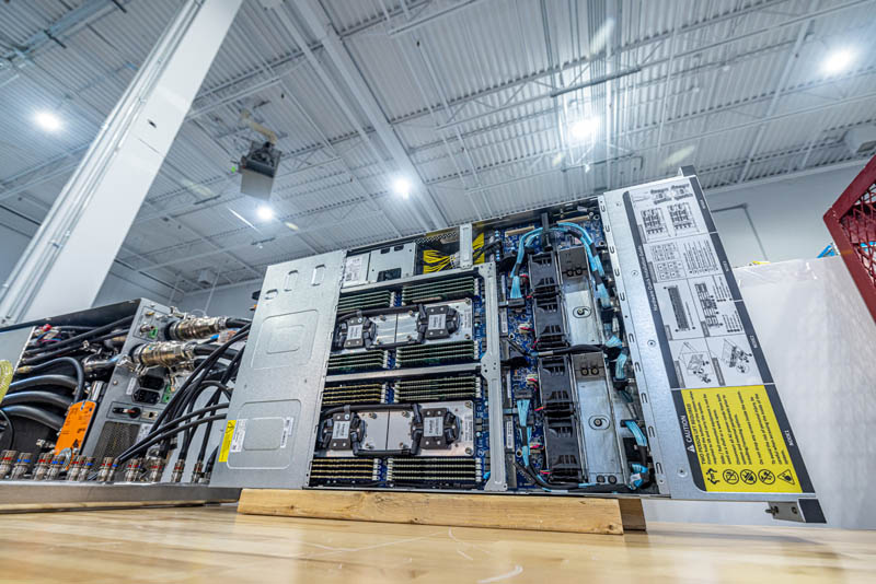
Once all four nodes are assembled, it is time to install them in the chassis and connect them to the rest of the cooling system.
Next, we are going to show how these fit together to cool the system.
Gigabyte H262-ZL0 and CoolIT CHx80
Once the four nodes were assembled, it was time to get the system running. This meant adding network, power, and for this system, additional liquid loops. This is mentioned in the video, but the Gigabyte server and the CDUs are not designed to run on their sides. Still, we were in the lab, and we figured it would work for a demo so that we could actually show what is going on.
We already covered that the cool liquid comes into each node via the blue quick disconnect connector and the warmed water exits via the red connector.
Both the red and blue connectors are connected to the rack manifold. These rack manifolds generally are mounted vertically in racks across from Zero U PDUs, but for our setup, we have a short one mounted horizontally on the table.
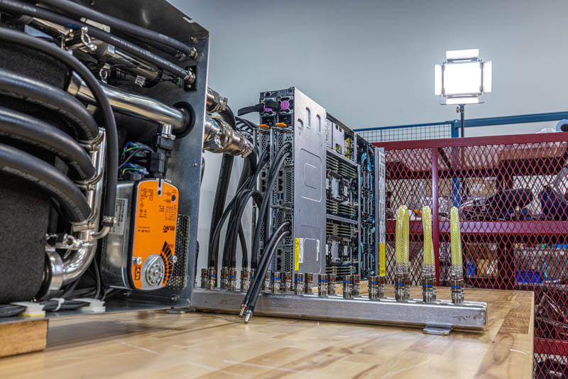
Here you can see the red and blue connectors showing the hot and cold sides of the rack manifold. When people say this is “water cooling” that is only somewhat accurate. The liquid in these systems have anti-bacterial, anti-corrosion, potentially anti-freeze, and other additives. We had three clear tubes installed from the cold to the hot sides just to show that this liquid is not clear water. Also, if water is used as a base here, it is often treated to remove contaminants before filling the loops.
The heart of the liquid cooling operation in a rack is the CDU, or Coolant Distribution Unit. We are using an older version of the CoolIT CHx80 here. This is an 80kW CDU able to cool around 40 of our test servers or roughly two racks of 2U 4-node 64-core AMD EPYC servers. We are using an older revision of the CHx80 because these are designed to be run horizontally in a rack and this vertical setup was one we thought would look better, and that it would not break, but we were not exactly sure if that was the case since this is not how the CDUs are designed to be operated.
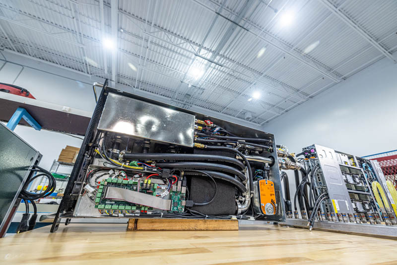
In the video, we go into exactly how the CDU works. Basically, cool water comes into an inlet from the facility and is run through a heat exchanger where heat from the server loops is transferred to the facility water loop and exits to the facility. Normally this would go to some sort of chiller as we showed in our Touring the PhoenixNAP Data Center article. We did something different as we will show in a bit. Other key components of the CDU are a reservoir to ensure that the pumps always have liquid in them. There are three pumps for redundant operation. A three-way valve is used to regulate flows in the system. Finally, there is a control and monitoring solution that can see the flow rates and cooling capacity of the system among other management activities.
The key takeaway is that there is a loop for facility water, then a separate loop that extracts heat from servers. A CDU manages the heat exchange between these two loops so the excess heat can be removed from racks.
We are going to have a follow-up article and video in a few weeks showing how the CoolIT Systems Liquid Lab that we are in tests components to ensure they are reliable and do not use the “L-word”. As you can imagine from the photos, there are a huge number of components inside servers, for the rack manifolds, PCLs, fluids, additives, tubing, fittings, CDUs, and more. We did this in the lab where all of that gets tested beyond specs so it can be built reliably. Stay tuned for that one.
Next, let us get to the performance, and the impact of this liquid cooling before we get to our final words.


Per the server cooling concepts shown in this article, my 2012-2021 gig as Sys Admin / Data Center Tech with the last few years immersion cooling infused, upon testing a system like the one shown here myself, I felt I was drifting towards being a Sys Admin / Data Center Tech / Server Plumber.
…Seeing my circa 2009 air-cooled racks with less and less servers-per-rack over time, and STH’s constant theme of rapidly increasing server CPU TDPs, data center techs need to get used to a future that includes multiple forms of liquid cooling.
This begs only one question: How much energy and water use for data centers (and coming soon/arrived to home users with the next gen nvidia gpus and current course of cpus) will break the camel’s back?
While it’s great that everything has become more efficient, it has never lead to a single decrease in consumption. A time during which energy should be high on everyone’s mind for a myriad of reasons and the tech hardware giants just keep running things hotter and hotter. I’m sure it will all be fine.
Amazing article. I’m loving the articles that I can just show my bosses and say ‘see…’
Keep em coming STH
P2 has really nice photos of the pieces. I’m liking that.
Very informative. The flow of useful informations was steady and of a high quality.
Awesome!
Patrick, next time you get your hands on something like this, could you try and see if you could open one of the PCL’s coolers. As a PC watercooling enthousiast, I’m curious to see whether the same CPU cooler principes apply. Particularly considering things like flow rate and the huge surface area of EPYC CPU’s.
Furthermore, it might be funny to compare my 4U half-ish depth water to air “CDU” with flow rate and temperature sensors with the unit you demonstrated in this review. Oh, my “CDU” also contains things like a CPU, GPU, ATX motherboard ;-)
How much power would the chillers consume though? This is definitely a more efficient way to transfer the heat energy somewhere else. I’m not so sure about the power savings though.
Bill, it depends, but I think I just did back of the envelope on if you did not even re-chill the water and just passed water through adding heat. It was still less than half the cost of using fans. Even if you use fans, you then have to remove the heat from the data center and in most places that means using a facility chiller anyway.
Would have been interesting to know how warm the liquid is going in and out. Could it be used to heat an adjacent office or residential building before going to the chiller?
With high-density dual-socket 2U4N modules, for example, there seems to be one socket which gets the cooled first and the exhaust of that cooling used to cool the second.
If I understood the plumbing correctly the water which cools the first socket in the setup tested here is then used to cool the second socket. RAM is air cooled but again the air is passed over the first group of DIMMs before cooling the second.
Under load I’d expect there to be a difference in the temperature of the first compared to the second. In my opinion measuring this difference (after correcting for any variations in the chips and sensors) would be an meaningful way to compare the efficiency of the present water cooling to other cooling designs in similar form factors.
How about the memory cooling, storage, and network? You still need the fans for that in this system.
With DDR5 memory coming up and higher power there will be a much smaller savings from a cpu only liquid cooled system.
Any chance to publish the system temperatures too?
Thanks!
Mark, mentioned this a bit, but there is another version (H262-ZL1) that also cools the memory and the NVIDIA-Mellanox adapter, we just kept it easy and did the -ZL0 version that is CPU only. I did not want to have to bring another $5K of gear through customs.
Very insightful and informative article.
I just finished re-building my homelab based on a water-cooled Cray CS400-LC rack and the power of water cooling is just amazing.
Certainly on this scale a very interesting topic from an engineering standpoint.
The commentary here is equally as good as the article. Depending on the physical location, the building envelope, and sensible load generated by the equipment, would be interesting to see a energy simulation/financial model of various design concepts for 1) the typical air cooled design 2) PCL shown above 3) immersion cooling w/ chillers or 4) (my personal favorite design concept) immersion cooling with a cluster of large oil reservoirs as thermal batteries. The cooling loop is switched between reservoirs for the heat transfer schedule. No fans. No chillers. Just 2 pumps and a solenoid manifold bank. This would work great in areas such as Northern Canada.
Comments are closed.