Gigabyte R113-C10-AA02 Internal Hardware Overview
Once we crack open the R113-C0, the inexpensive nature of the system becomes self-evident. Rather than a bespoke solution, the R113-C0 appears instead to be a more generalized chassis populated with largely off-the-shelf components.
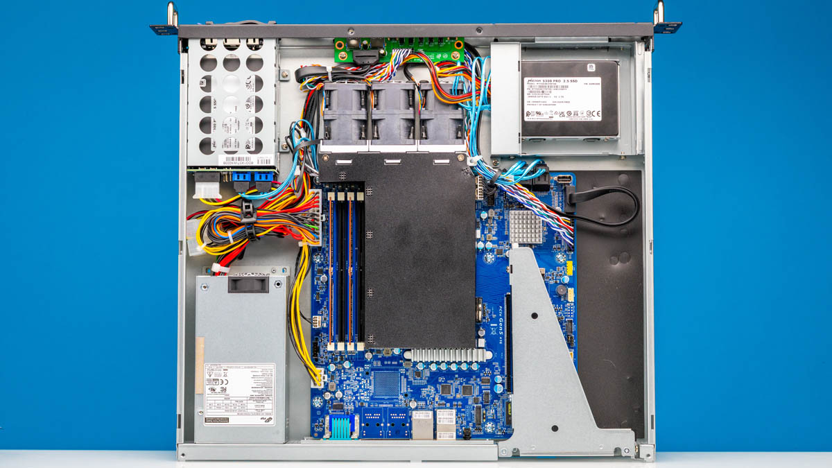
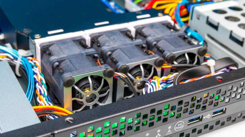
Starting front and center, we have three fan pairs that provide the majority of the airflow in this chassis, almost all of which is directed through the air guide over the CPU heatsink.
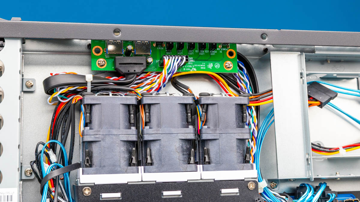
These fans are replaceable if they should fail, but doing so is not easy and they are not the click-in hot-swap type of fans you might expect in a higher-end system. Directly in front of those fans is a small PCB handling the front I/O, buttons, and indicator LEDs.
Because this is a less expensive server, there the storage backplane is very simple.
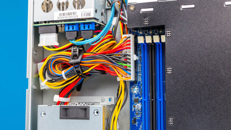
Additionally, there are a pair of SATA III 2.5″ fixed bays. These rely upon cables instead of a backplane and are not hot-swappable.
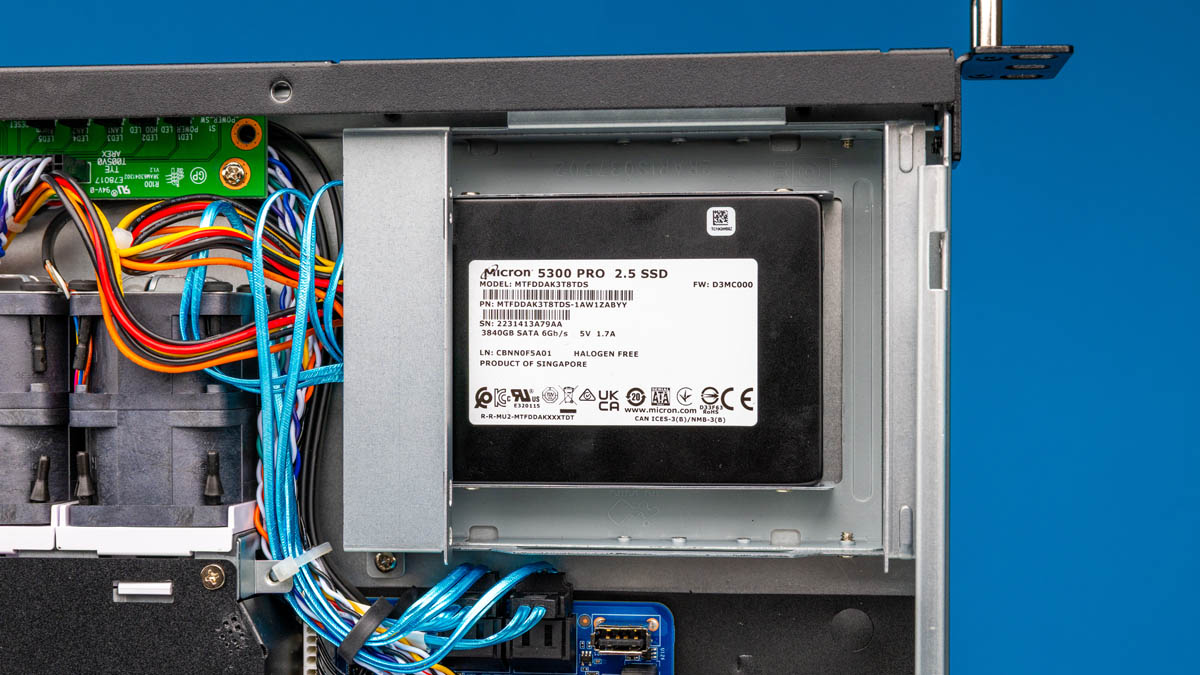
My test system was populated with 4x 3.84TB Micron 5300 PRO SSDs which added up to a respectable amount of total storage, but the half installed internally would be difficult to service in the field.
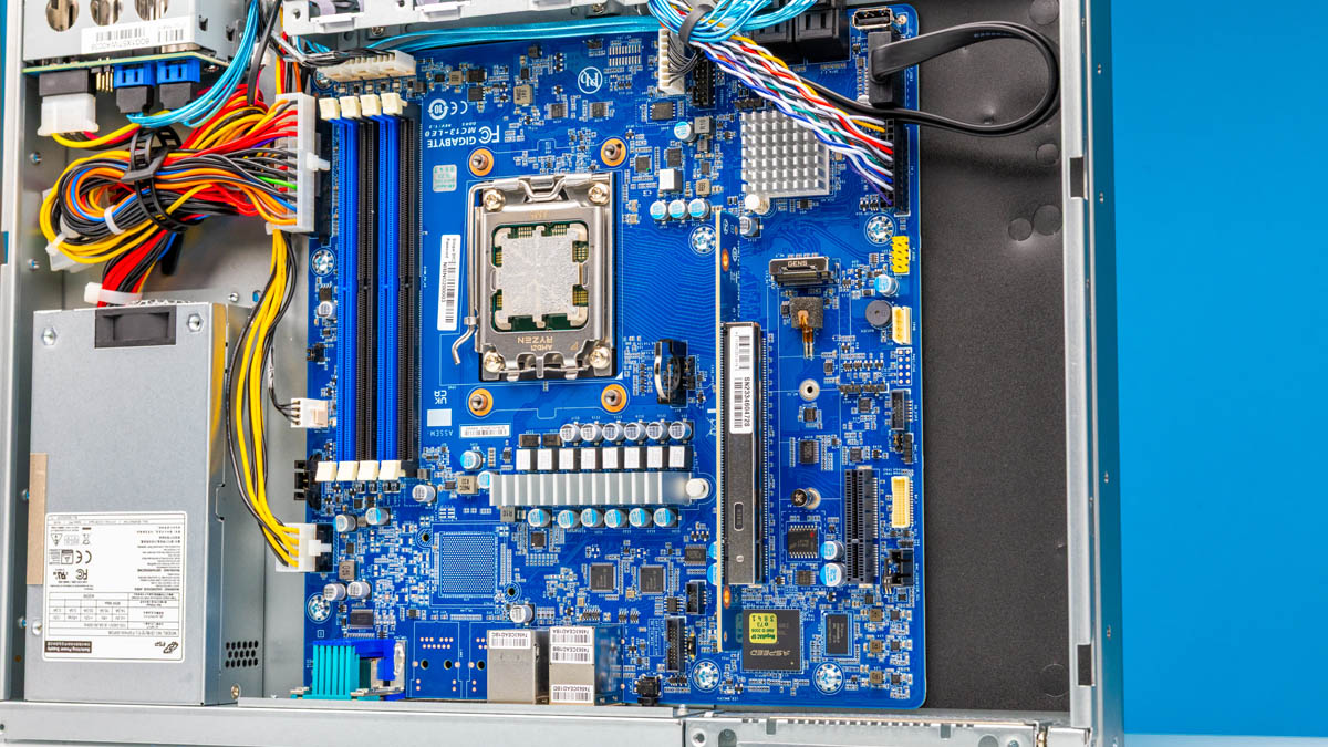
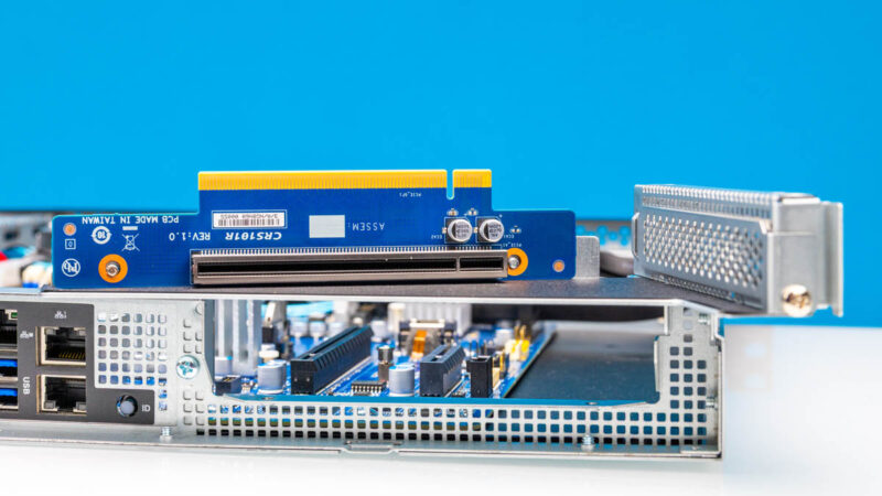
This system is built around Gigabyte’s MC13-LE0 motherboard. The MC13-LE0 is a mATX B650E board featuring four DDR5 memory slots, a PCIe Gen5 x4 M.2 slot, and a Gen5 x16 PCIe slot.
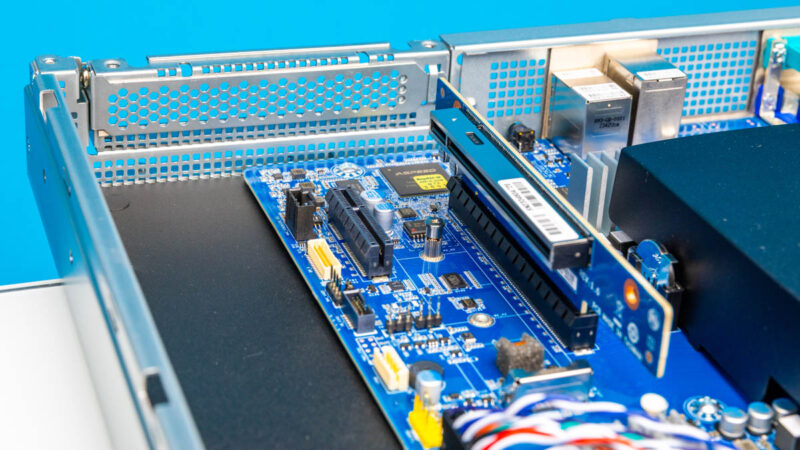
There is also an additional Gen4 x4 slot, but in the 1U configuration, that slot is inaccessible.
Unlike some higher-end servers, the PCIe riser requires removing screws to service. Again, this is a cost-optimized server, so you pay less for having more screws.
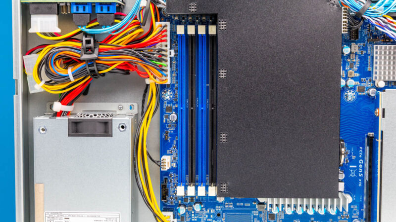
The AM5 CPU socket on the MC13-LE0 motherboard supports Ryzen 7000, 9000, and EPYC 4004 series processors at up to 170W TDP, though it should be noted the 1U cooling solution on the R113-C0 is limited to a 105W TDP.

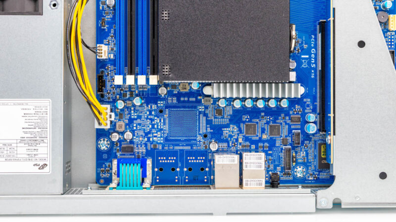
The four memory slots support up to DDR5 5600, and the exact specifics for what is supported depends upon how many memory slots are occupied and which CPU is installed, so you would want to check Gigabyte’s published specifications for yourself to determine your own ideal configuration. You can also see our Why One DIMM Per Channel or 1DPC Can Be Great for AMD EPYC 4004 piece. We managed to get 4x 48GB for 192GB total working in this system.
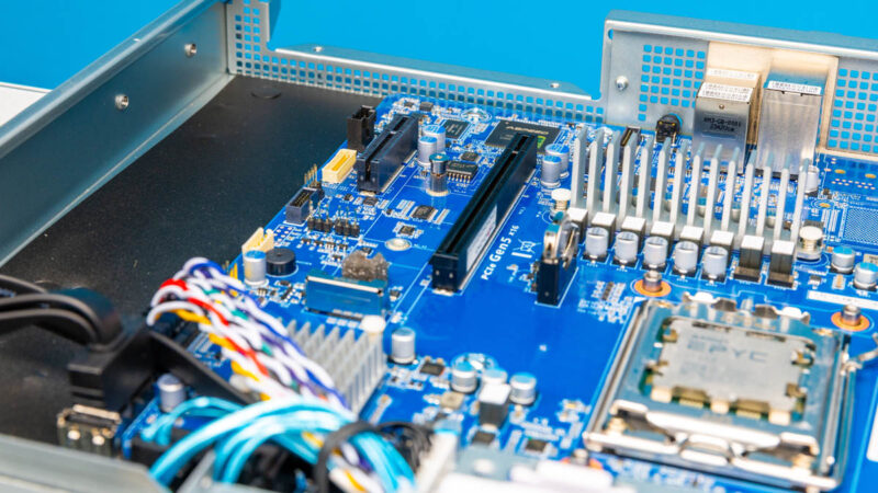
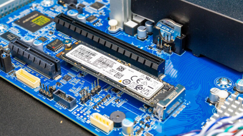
SATA storage is perhaps the primary storage option given the four SATA drive slots, but there is NVMe capability as well. As mentioned there is a single Gen5 M.2 slot, which I utilized as a boot drive for my testing.
Since this is a cost optimized version, higher-end networking is not populated and instead we simply have the two 1GbE NICs here.
Next, let us move to the topology and management.


Small typo:
“As mentioned previously, the Proxmox VE 8 worked fine in this configuration and we tested it with up to 196GB of memory.”
I’m guessing you either meant 96GB or 192GB. Not sure what kind of configuration would get you 196GB.
@James, thanks! I’ve fixed it.
@James 6x32GB sticks and a 1x 4GB or 2x 2GB would give you 196GB :)
What is the noise like under moderate load? I am trying to determine whether this would be a suitable platform to build a proxmox ceph cluster in my homelab where noise is a consideration.
Comments are closed.