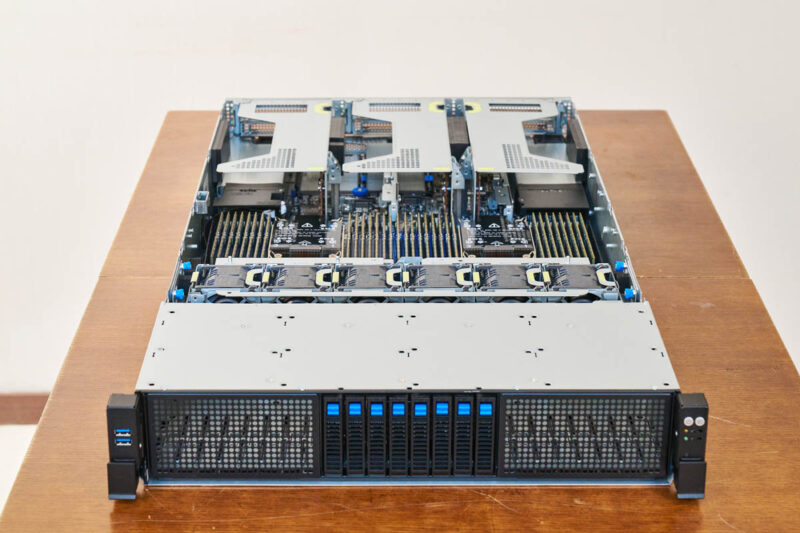
ASUS RS720-E12-RS8G Internal Hardware Overview
We are going to start at the front of the system, and work our way to the back.
The backplane for the front eight NVMe bays is fed via MCIO connections that run under the fan partition.
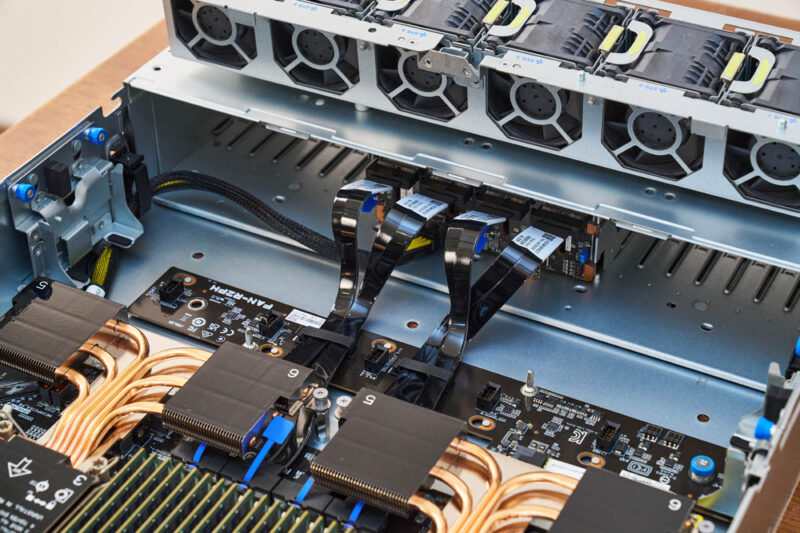
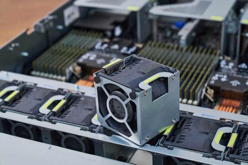
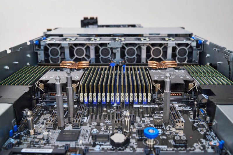
The fan partition has six dual fan modules.
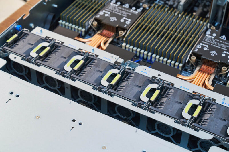
Each of these modules is hot swappable.
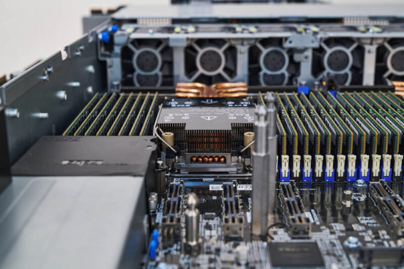
There is an airflow guide that keeps the bottom airflow for the CPUs, memory, and NICs, and then the top for the PCIe slots, which can be GPUs. That is why the airflow is bifurcated like this.
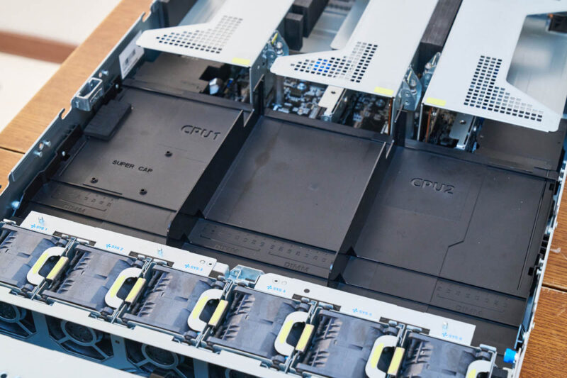
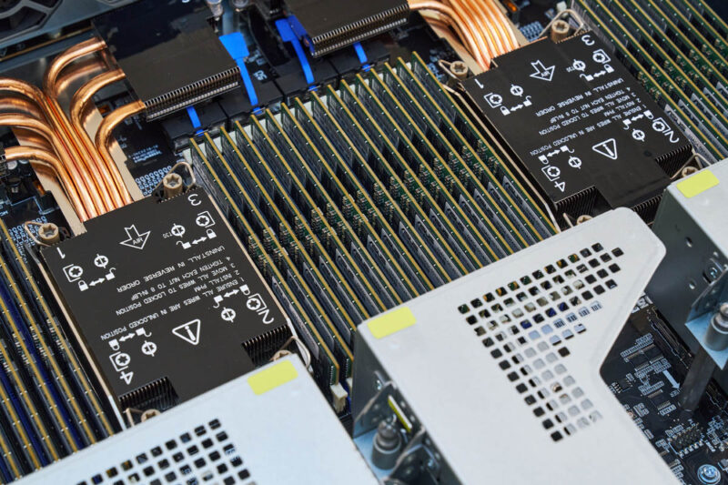
On the bottom, there is the dual Intel Xeon 6700 series setup. This system can take either Intel Xeon 6700E or Xeon 6700P series CPUs. That means one can optimize for up to 288 E-cores or instead optimize for P-cores.
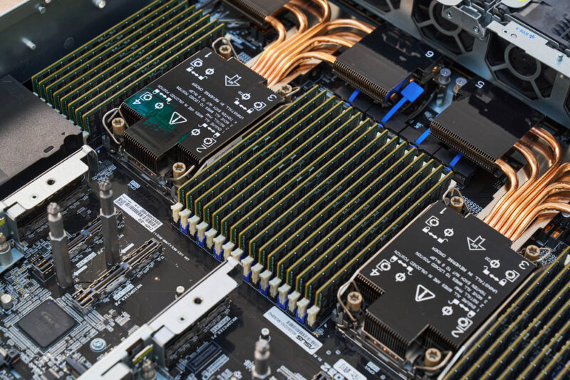
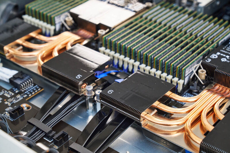
The heatsinks are 1U designs even in the 2U chassis, so to get extra space, there is an array of heatpipes to the front sections of the heatsinks.
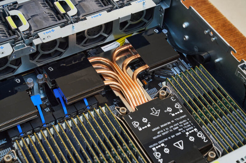
These front heatsinks in the center are raised so the MCIO cables carrying PCIe to the NVMe front bays can pass underneath. This is a really cool design.
In terms of memory, we get 32x DDR5 DIMM slots since the Xeon 6700 series is an eight channel design. With two DIMMs per channel we get 16 DIMMs per socket or 32 DIMMs total. With the Xeon 6700P series, these can be MCR DIMMs/ MRDIMMs.
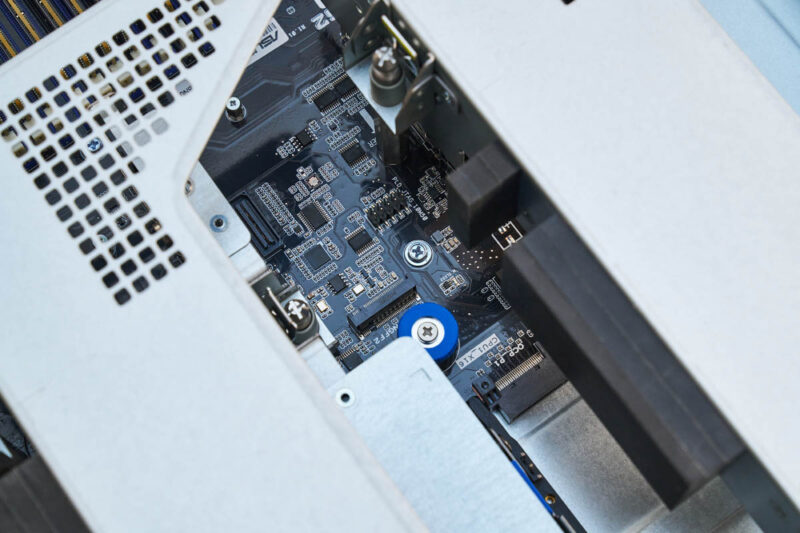
Onboard, we have a M.2 slot underneath the rear riser section.
Here is another look at the risers installed.
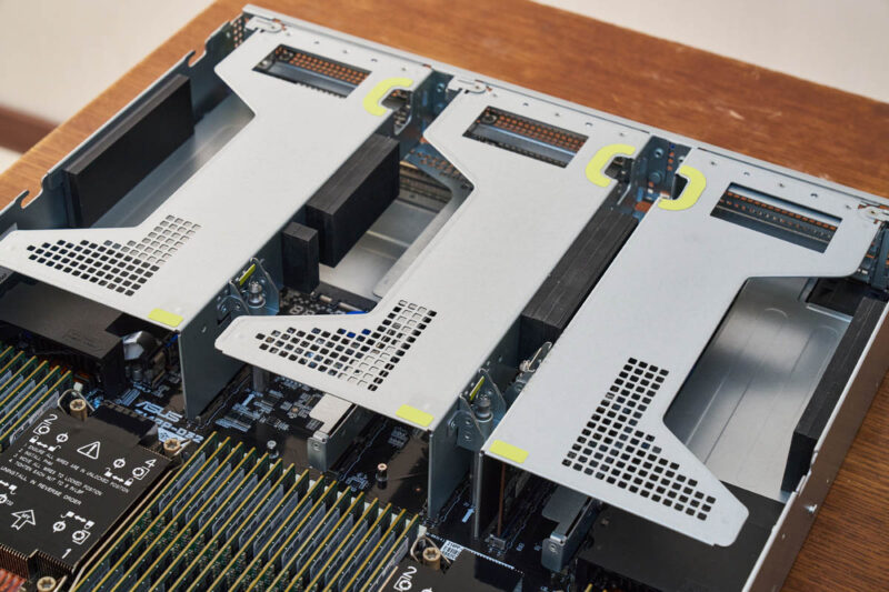
Here is a quick look at the riser slots and the POST code display. ASUS has had these little POST code displays for years.
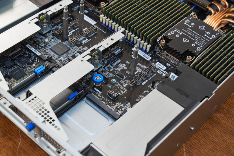
With he risers out, here is a look at the CPU heatsink from the rear of the chassis.
Here is a view from the center of the chassis with the metal posts that guide the risers in place.
On the bottom rear, there are two OCP NIC 3.0 slots with internal latches.
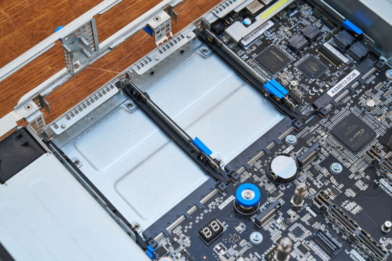
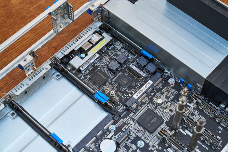
Here is the DC-SCM with the ASMB12-iKVM out-of-band management solution.
Next, let us get to the block diagram and topology.


Seeing the design of the CPU coolers makes me wonder how well the memory modules standing right behind the extended portions will tolerate the extra heat being blown over them long-term. Those bits don’t run cool and the RAM is already running at speeds hot enough to require their own cooling system. Anyway, neat looking dual LGA-4710 system.
The design language of the PCBs is the classic ASUS mainstream one down to the fonts used, and of course black solder mask. Even half of RAM slots are black and the other half is blue. There are a lot of matching blue components from jumpers to SSD latches which contrast with the black components.
It looks like they actually care about how the server looks both externally and internally, it’s quite refreshing.
With Dell using the DC-MHS this is almost the same except it’s got another OCP NIC instead of the BOSS, ASUS is using 2.5″ not E3.S, and they’ve got standard IPMI instead of iDRAC. If ASUS can build something that’s almost the same as Dell now, then what’s the point of paying more for Dell’s “engineering????” I don’t understand why the motherboards are almost the same.
3.2kW PSUs… wow. And I thought the 2kW PSUs in the GPU server I’m building for my homelab was a lot.
Comments are closed.