
The ASUS ESC A8A-E12U is a big server. With two AMD EPYC processors and eight AMD Instinct MI325X GPUs the system has plenty to offer. Beyond just those big CPUs, there are eleven PCIe slots and even the ability to add up to ten NVMe SSDs. This is a server we saw at OCP 2024 and SC24, but now we had hands-on time with it. As such, it is time for another AI server review.
We also have a short if you just want the highlights.
ASUS ESC A8A-E12U External Hardware Overview
The system itself is relatively compact for an 8-GPU air-cooled system at 7U and 885mm (~34.84in) deep.
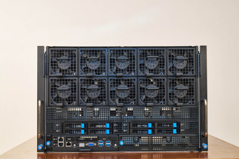
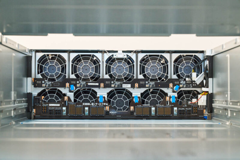
The front faceplate’s most eye-catching feature is probably its fan array.
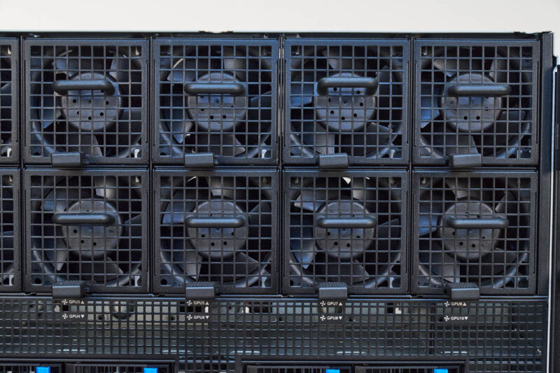
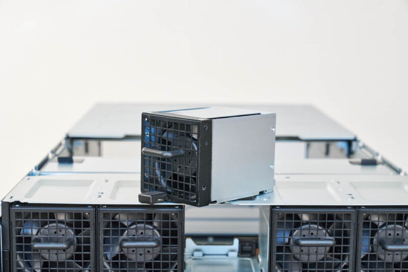
There are ten fan modules that are hot swappable.
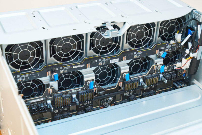
ASUS also has the fan power PCBs cut specifically to maximize airflow from these fans to the GPUs that reside in the top portion of this chassis.
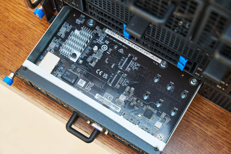
On the front left, we get four NVMe drive bays as well as our front I/O. The front I/O consists of four USB 3.2 Gen1 ports, a VGA port, two 10Gbase-T ports via an Intel X710 NIC, a management LAN port, and even a Q CODE display so you can see the POST codes externally.
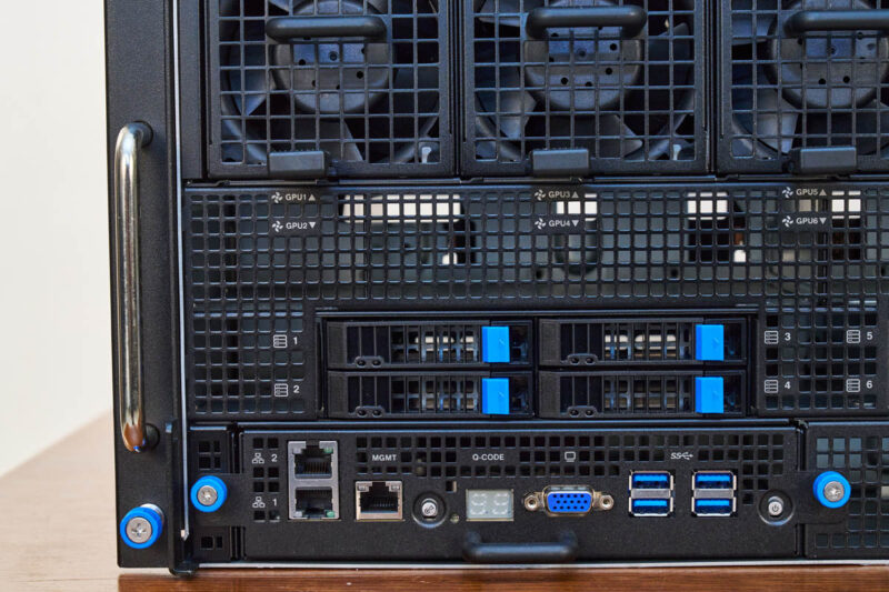
That front I/O is also on its own module that can be serviced from the front of the chassis.
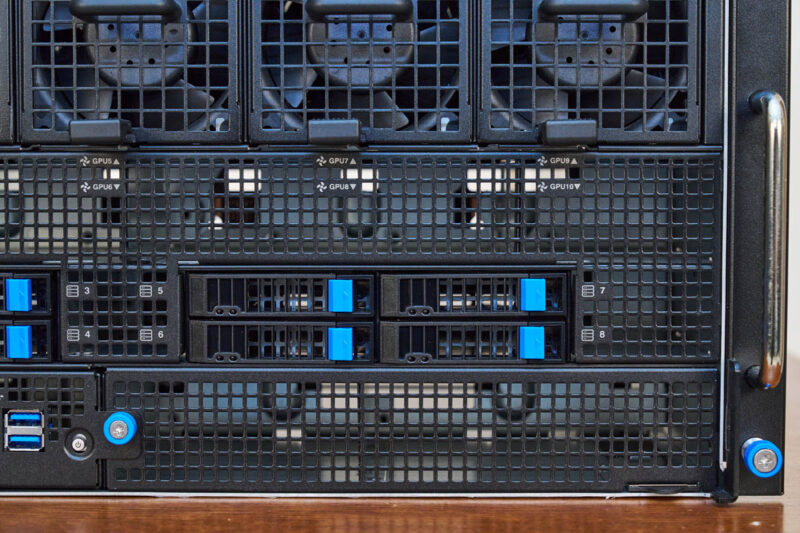
On the front right, we get four more 2.5″ U.2 NVMe drive bays for eight total, and then a lot of room for airflow.
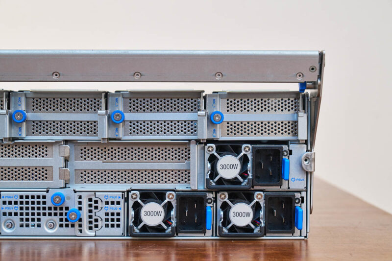
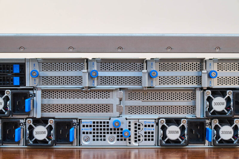
Moving to the rear, almost the entire rear is built around two trays. The top one is the OAM tray where the GPUs are housed. The bottom has the PCIe NICs and the CPUs.
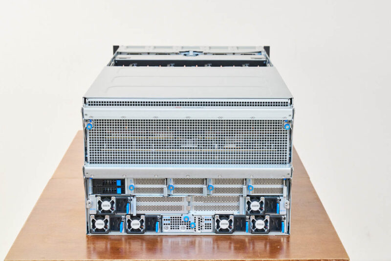
While the top part is just a grille for airflow, the bottom has our boot drives, power supplies, and PCIe card slots.
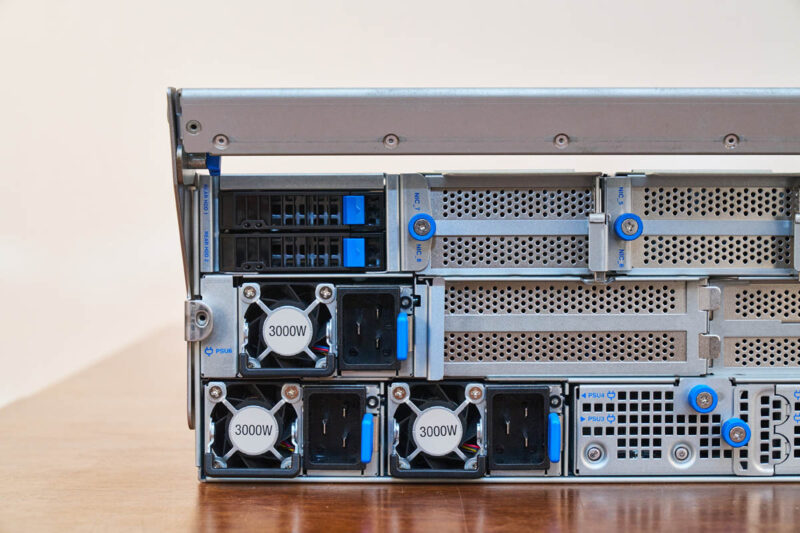
There are a total of six 3kW PSUS on the system. It is not set up for full A+B power. Instead, this is a 5+1 redundancy design that reduces the number and size of the power supplies.
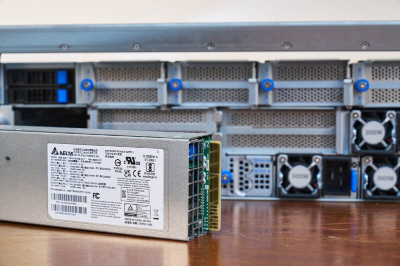
Here is a quick look at the Delta sourced PSUs.
The rear also has two 2.5″ bays, which are really for the OS boot drives.
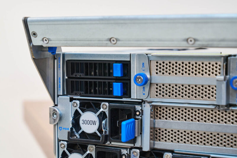
We will discuss the PCIe situation when we get inside, but you can get up to eleven PCIe card slots in this system.
The actual chassis, however, is effectively that front section, then the two areas for the two main trays in the system. This actually makes the system easy to service.
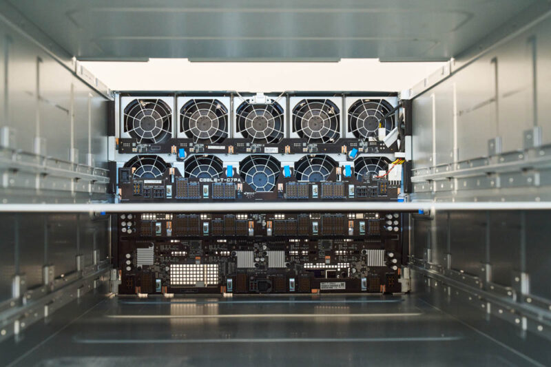
Here is the top portion where we can see those front hot swap fans as well as the UBB mating connectors for the GPU baseboard.
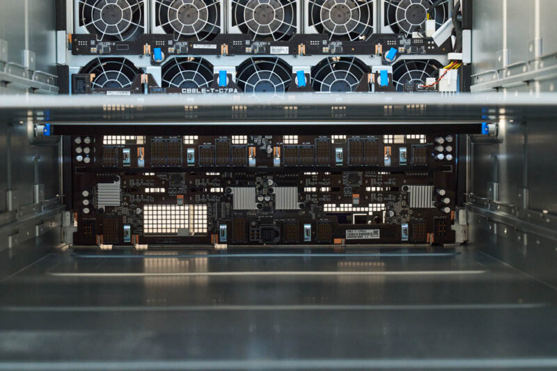
The bottom section has the connectivity for the CPU and PCIe card tray.
Next, let us see the motherboard tray and the MI325X GPUs.


Also the image link for the image captioned: “ASUS ESC A8A E12U Llama 405B FP8 On AMD Instinct MI325X 5K Tokens Per Second” is wrong. It takes you to a picture of a 10GbE switch from a different review.