
The ASRock Rack SIENAD8-2L2T is perhaps one of the most straightforward designs we have seen from the company. Built around an AMD EPYC 8004 “Siena” processor, the motherboard is designed to expose the platform’s functionality in a way our readers may get really excited about. As straightforward as the design is, it still has a little ASRock Rack design flair that our readers may have already seen.
ASRock Rack SIENAD8-2L2T Overview
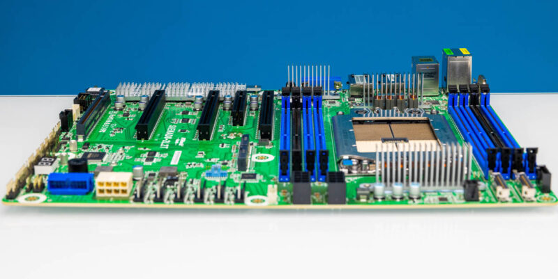
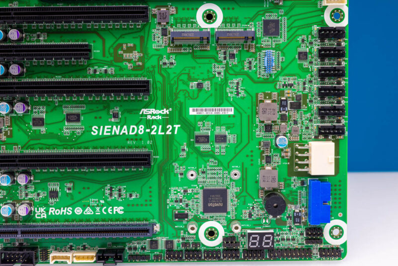
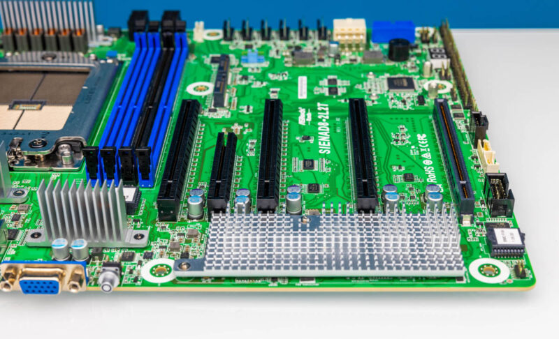
The motherboard itself is standard ATX 12″ x 9.6″ size. That makes it smaller than some of the other Siena boards we have reviewed previously.
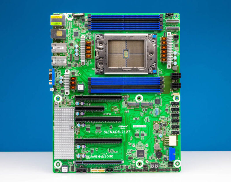
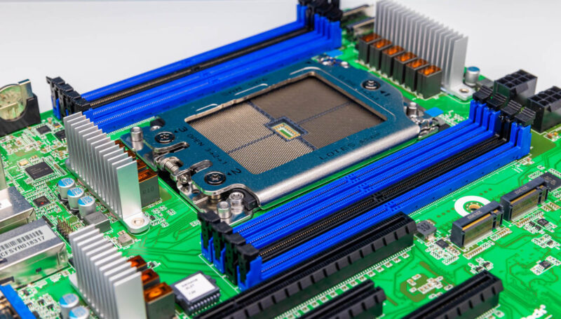
At the heart of the motherboard is an AMD socket SP6 (LGA 4844). What ASRock did with this motherboard is to make something that could be an upgrade to a 1 DIMM per channel AMD EPYC 7001-7003 series system or even an Ice Lake Xeon system.
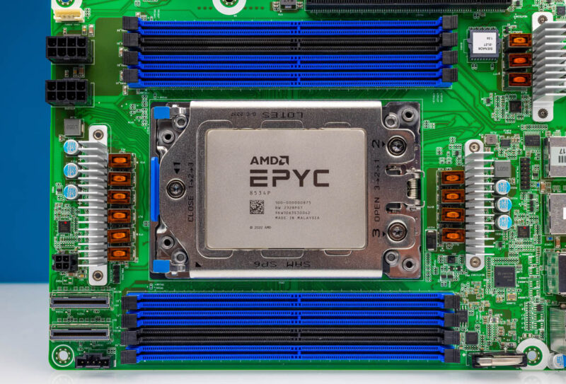
AMD sent us a number of CPUs to use. We are using the AMD EPYC 8534P 64-core 200W processor in this system for the photos. The AMD EPYC 8004 “Siena” series is fascinating as it has a ton of I/O and up to 64 cores in single socket platforms, but it uses Zen 4C cores and has less memory.
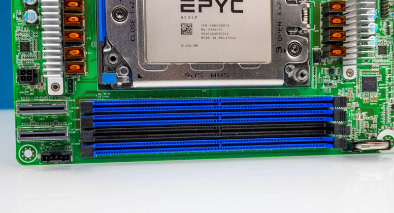
One of the big features of the AMD EPYC 8004 series is the DDR5 memory layout. The processor family supports 6-channel memory, half of the EPYC 9004 series. Instead of this being a strictly 1DPC or 2DPC design, ASRock Rack has an additional two slots for eight DDR5 DIMM slots total. That really helps when it comes to folks needing to migrate from older generation Xeon E5, Xeon Scalable, Xeon D-2100, or early generation EPYC 3000 or EPYC 7000 systems.
From an airflow perspective, this is an ATX server platform. As a result, is optimized for front-to-rear airflow.
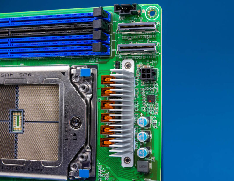
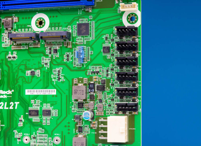
MCIO connectors have become very popular in the PCIe Gen5 era. This system has two at the top edge of the board.
Something you will not see on the motherboard is a standard 24-pin ATX power connector. Instead, there is a little 4-pin ATX Power connector. ASRock Rack includes an adapter for a 24-pin to this in order to provide features like power on for the system.
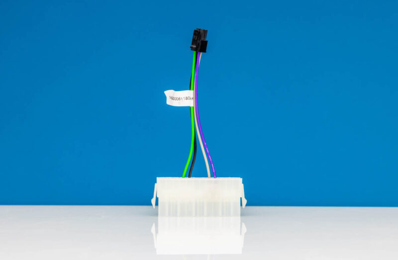
Instead, ASRock Rack is using two 8-pin 12V power inputs for the board’s power. Something we have seen from the company is that the traditional 24-pin power connector is too big to make dense designs, so this is a layout ASRock Rack has done for years. We promised some ASRock Rack flair.
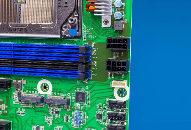
There are six fan power headers designed for traditional 4-pin or larger counter-rotating fan designs. These are neatly placed at the leading edge of the motherboard, where most fan partitions will be.
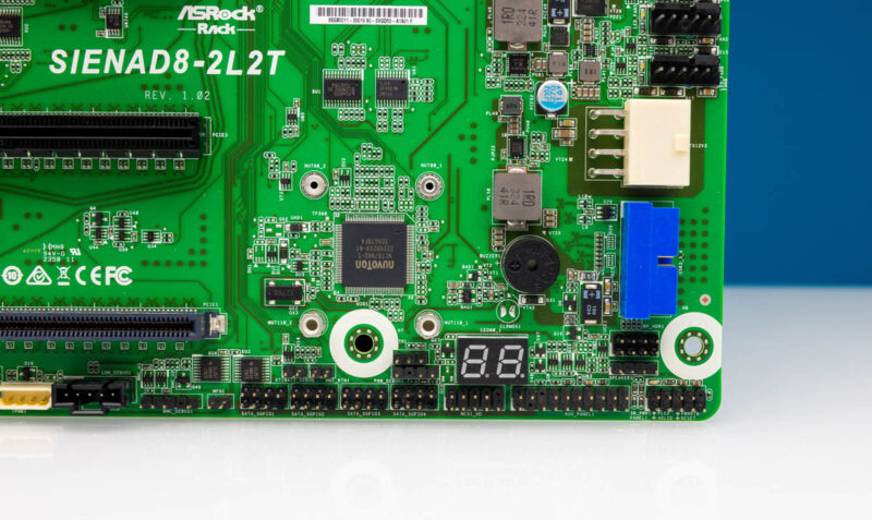
On the bottom of the motherboard, there is a POST code display and a number of headers.
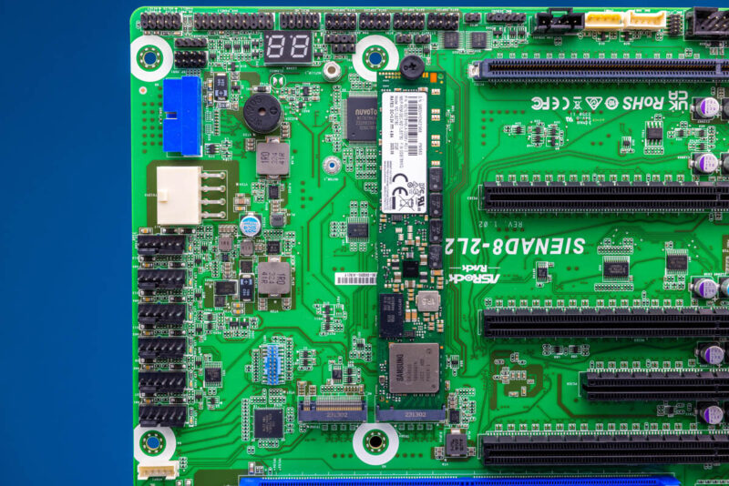
One of the neat features is that this motherboard has dual PCIe Gen5 x4 M.2 slots. These slots can be either M.2 2280 (80mm) or 22110 (110mm) depending on where the mount is installed.
ASRock has a nice thumb screw, but we wish that the mounting point was a tool-less design. Some other manufacturers have started to have tool-less M.2 mounting all the way from securing the drive to the mount as well as securing the mount to the right spot on the motherboard. It is a small touch but it would save a few seconds per installation.
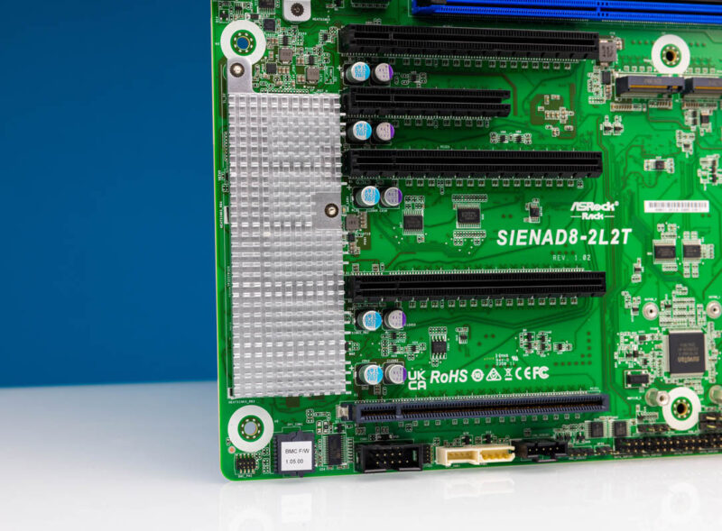
This platform has four PCIe Gen5 x16 slots, three of which support CXL 1.1. These slots are spaced for double-width cards, and there is even an x8 slot. The block diagram section will explain how all of the PCIe is connected.
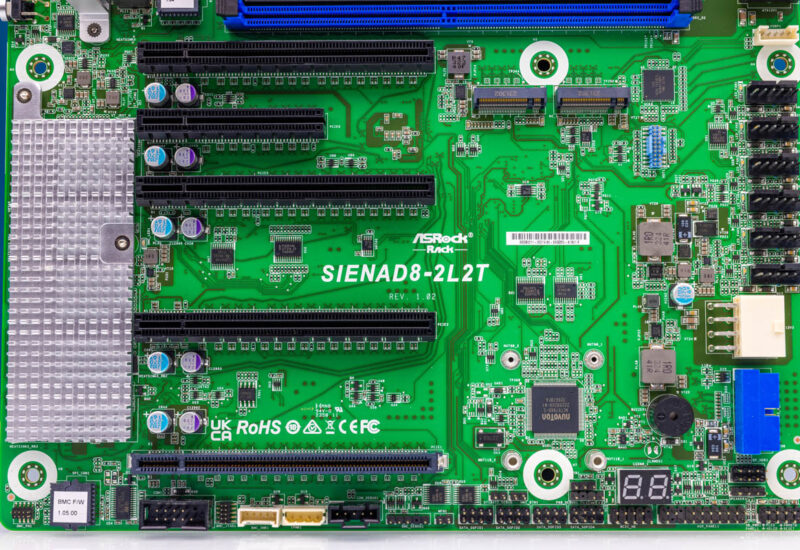
Here is another look at the PCIe slots. Something we should point out is that full-length PCIe cards will cover the onboard M.2 slots.
Under the heatsink, there are two main chips. First, there is an Intel X710-AT2 controller (top) for 10GbE. The second is an ASPEED AST2600 BMC (bottom). A single heatsink covers both.
Another fun design element is here with the Intel i210-AT NIC for 1GbE.
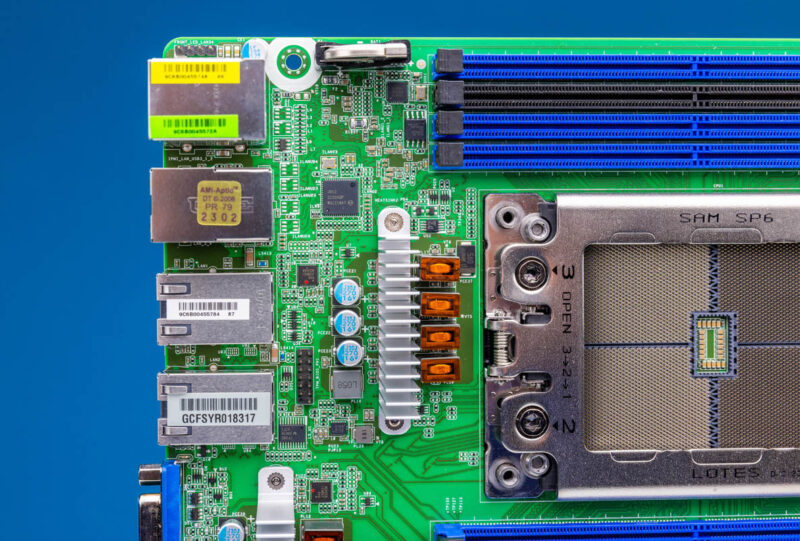
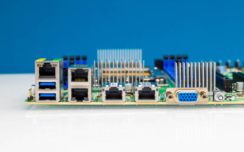
The rear I/O has the out-of-band management port, as well as VGA and two USB 3 ports for local access. There are two 1GbE ports and two 10Gbase-T ports for a nice mix of 1GbE and 10GbE.
Next, let us get to the block diagram.


It is indeed a straightforward design. 7 pin SATA means exactly that – 7 pin SATA. Might be my first time seeing that!
As for SATA routing, is it possible that you just give up that noted PCIe slot while using the 7-pin bare SATA headers at the bottom of the board for cabling? Again, I’ve yet to see SATA headers like this.
Looks really interesting to pick up secondhand in a few years. If sold or purchased thru such channels, would the login/password reset to admin/admin?
Hey Patrick! No offense, but where is benchmarks, that one bench chart don”t counts?! Where is power consumption graph, pointless review. Where is comparison table where we can see what features supermicro offers for diy folks , lets say with x13 and Enerald Rapids. Sorry but thats low quality article. Thats my opinion.
and whats the main differences between integrated nics on various platforms lately, some choosses Broadcoms, some x550, some X710.?! Thats worth to deepdive and make seperate article, with power consumption features etc
How much traffic we can push thru discrete nics, lets say, mellanox4, 5 , 6 or , how much Gb /s that various platforms using if all ports populated with u.2 drives?
SERVE THE HOME -right? i hope this site is still for diy folks…..give us numbers, more benchs, less bulshit.
Can we get some power consumption figures for the Siena cpus please
Perhaps there is a breakout board forthcoming for the 16x SATA capable slots. Since this is PCIe it would be cool if they actually supported 12gigabit SAS as well as SATA. The PDF user manual does show them in it’s BIOS description. It also notes the existence of four SATA 7-pin headers but says nothing more about them. Nothing about how the MCIO can be configured.
Interesting board.
SATA can be accessed with a card similar to this (sorry can’t find the specific one): https://www.asrockrack.com/general/productdetail.asp?Model=RB1U2SL#Specifications
Should be 1U2G-RB1U2SL-4G.
Any idle power usage numbers for this motherboard and platform? It’s one of the key features over higher power usage servers!
As far as SATA, the manual (page 7/8) says the onboard headers are SGPIO, which I believe would be for enclosure status LEDs. Page 22 also references a RB1U2SL riser card for SATA (https://www.asrockrack.com/general/productdetail.asp?Model=RB1U2SL#Specifications), though I don’t see it for sale anywhere
@Gasmanc we usually do power consumption on whole systems, instead of just motherboards. In a system like this, figure ~200W for the 64C CPU (Siena stays close to TDP more like Bergamo) but then 30-40W for DDR5, tens of watts for the fans, PSU power loss, and so forth. You end up with 50% more power just to get the system powered on than the motherboard takes, and that would be in a bench design. A server would be more due to additional fans for example.
@laughingman These days most server platforms are thermal limited. It is less like the consumer side where there are huge variances. When we set systems up with the same CPUs and settings, we expect a +/- 3% variance with different CPUs across a range of tests. I am not sure what reviewing NICs not on the motherboard accomplishes. Pushing traffic on a CX-6 is line rate in a platform like this so that is not going to accomplish anything. Where are the U.2 drive bays on this motherboard? We can just make up random metrics, but we try to keep it close to the product being reviewed and what differentiates them, not just random thoughts. Figure 100K+ folks will see this review. I take very seriously trying to stay near the product since that is a lot of people who I do not want to introduce random thoughts and waste time for the majority of them.
If we just want Siena power, we are going to have another server review soon with it.
I was curious on how the SATA ports worked. Page 22 of the user manual has a diagram of a riser that goes into the x16 slot and has two connectors for break out cables for the SATA interface. The 0.1″ pitch headers on the bottom of the motherboard are for SGPIO.
If you search for the riser part number 1U2G-RB1U2SL-4G R1.00 a different ASRock Rack system comes up with what looks like this, or really similar, riser in it.
Still, why put the SATA ports in the slot that needs a riser and not the MCIO connector already on the motherboard? Maybe the connector height would be too tall for a 1U chassis?
Rewording and summsrizing the manual isn’t much of a review. The coverage of anything Siena related has been a summary of the press release or product manual at best.
So this motherboard has two DIMMs on CHD and CHH but the four other channels have only one. While a person could leave the black socket unpopulated, I wonder if the Linux memory allocator makes reasonable choices about memory from the shared channels.
Said another way, the NUMA of EPYC processors is already so complicated that the shared DIMM channels might be more a gimmick than something useful.
While optimising such a memory architecture is likely out of scope, it would be interesting to characterise the applications where populating the black socket made a performance difference. Such results might help satisfy people posting above concerning how they want to hear more than what appears in the manufacturer’s documentation.
@Eric
In the default configuration the allocator has no knowledge of the memory topology, it has a map of valid physical memory addresses and that’s it. It’s the job of memory controllers in the CPU to manage optimal placement.
Software control is possible only with NUMA, and even then it heavily depends on the implementation.
I’d imagine the two dual-DIMM channels are there for use cases requiring more RAM for the price of slight bandwidth reduction (when compared to more single-DIMM channels). Probably ASRockRack had place near the socket to spare, so why not. I’ve seen Intel Supermicro boards doing the same thing.
Admittedly an edge case here, but has a Threadripper or Threadripper Pro CPU been dropped into this board? I am curious what the unofficial interoperability is with Siena and AMD’s workstation parts on a board like this is. (Of course the official support is no but has anyone tried it?) I want to know mainly because AMD is doing some interesting segmentation between these platforms like Siena leveraging Zen4c chiplets for increased density/lower power while Threadrippers use the vanilla Zen 4 chiplets for higher clocks. I suspect that with Zen 5 and Zen 6 on the horizon, AMD will be distinguishing these platforms with differences in V-cache and accelerators.
@Mike, @Mama, @ajr – thanks for the breakout board info. I did look for something like that on asrockrack site but I had no luck.
Does anyone know when this will actually be readily available? I’d love to build a server with this mobo and the 8224p.
“It is a small touch but it would save a few seconds per installation.”
Please! No manufacturers custom tool-less mounting mechanism. The M.2 drive cooler incompatibility is not worth a few seconds per installation.
I’m planning to just plant 3 PCIe to 2x MCIO8i onto the board, use two of those for NVMe storage, and the third with two MCIO to SATA adapters.
Since it’s a dumb adapter, and each data lane is just signalling SATA instead of PCIe, I would expect this to be the most flexible breakout, as it would allow me to switch to additional NVMe in the future, with the highest likelihood of still getting at least reliable PCIe4 off those lanes.
Would appreciate if anyone else managed to get SATA off this board, as decent 16x HBAs are going to inflict even more damage to an already well over-budget build.
Also, does anyone know if this supports PCIe hotplugging? With MCIO and nvme backplanes, this should be a common feature by now, but documentation is non-existant.
This breakout card works to get 16 SATA connectors per PCIE slot: https://www.aliexpress.com/item/1005007110631377.html
Here’s a cable, you need 4 per card: https://www.aliexpress.com/item/1005005831252365.html
There’s a bunch of “hotplug” settings for PCIe, MCIO and NVME in BIOS.
What is contained in the package if you buy the board. For example if it contains some MCIO U2 connectors the board would kinda become cheap
I tried to get SATA links via a Kalea Informatique PCIe to MCIO adapter in combination with a 10Gtek MCIO-SATA breakout, and that failed.
The same card works fine for breaking out x4 PCIe links, so I am a bit confused what could be going on – maybe some signal filtering.
New SIENAD8-2L2T / AMD 8224 to my UnRaid system. I am having real troubles with the PCIe cards & the Intel X710-AT2. Installing a PCIe card (Broadcom HBA or Intel A310 GPU) in any of the PCIe slots and the twin 10G network dies and the IPMI logs “Asserted Event Data1 PCI PERR Event Data2 PCI bus number for failed device: 0x01 Event Data3 PCI device number: 0x00, PCI function number: 0x00” errors. These cards work fine in an older Supermicro board. I’ve tried disabling the CXL support and ASPM support on the PCIe slots to no avail. What am I missing?
Comments are closed.