
Always looking for a better PDU for our labs, we recently took a look at (and took apart) Ubiquiti’s USP-PDU-PRO. A 2U PDU with a mix of both standard North American AC outlets and USB-C ports for DC power, the USP-PDU-PRO is designed to synergize with Ubiquiti’s other networking products and its UniFi ecosystem. Fittingly, while this is first and foremost a power distribution unit, it has quite a few features that we normally do not find on other PDUs.
As a quick note, this is not a mini-review sponsored or supported by Ubiquiti since we did not sign the NDA they provided to STH. This is just a unit that we purchased and decided to do an overview with it.
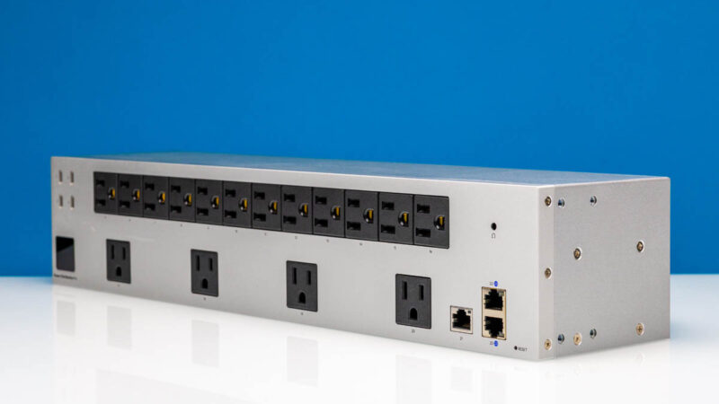
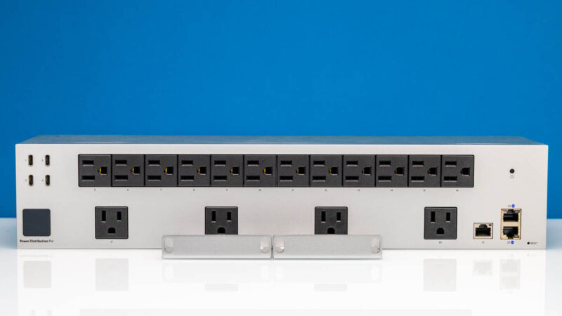
Ubiquiti USP-PDU-PRO External Hardware Overview
Starting from the front of the USP-PDU-PRO, we find 16 NEMA 5-15 sockets. 12 of them are lined up in a dense formation along the top row of the PDU, while 4 more are spaced out along the bottom row.
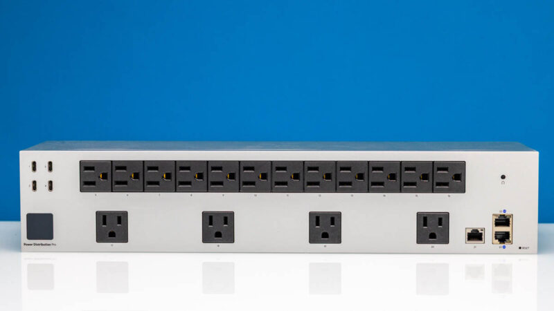
Focusing on the left side, here is where we will find 4 USB-C ports as well for providing energy to low-power USB devices. Each port is limited to 2A@5V (10W), with the entire cluster of ports limited to 20 Watts overall.
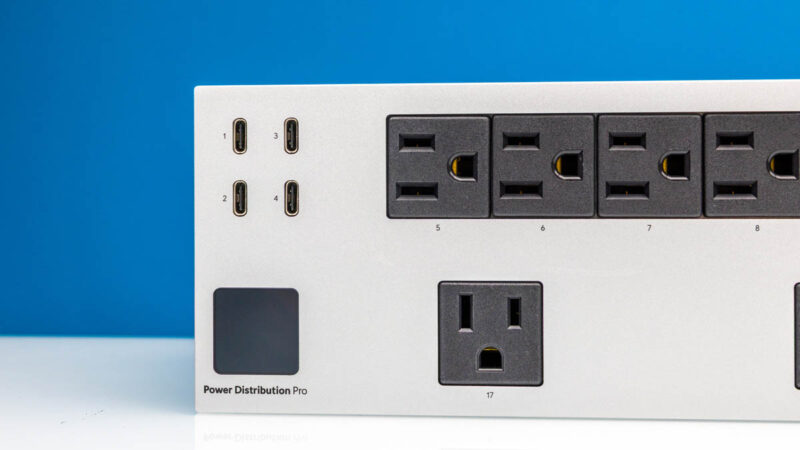
As we will see, this is fed by an internal 40W power supply, whose output is split between these ports and all of the other active features of the PDU.
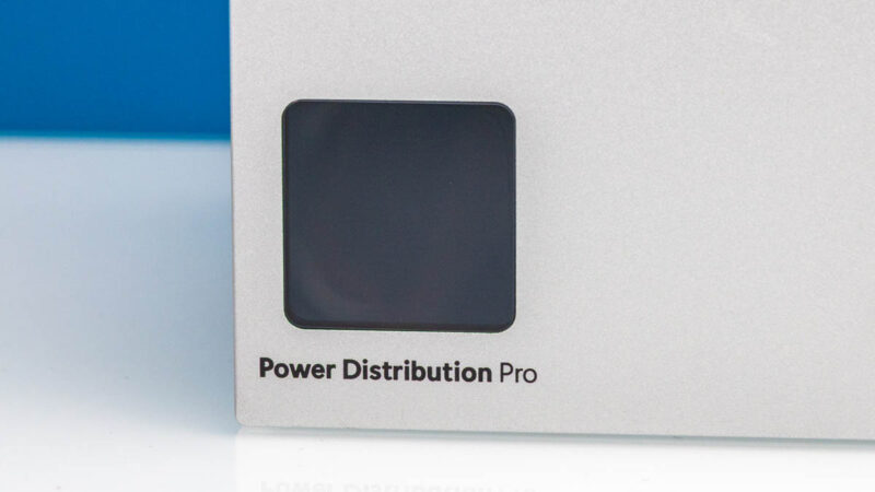
On the lower-left side, we see one of those features with the 1.3-inch touchscreen, which is used for basic control of the PDU. Other than the circuit breaker and the factory reset buttons, there are no other controls on the USP-PDU-PRO, so the touchscreen is everything (at least until you get networking up and running).
On that note, on the lower-right corner of the PDU we find three of the PDU’s four RJ45 Ethernet ports. The side port operates at 100Mbps, while the two top-to-bottom ports are full GbE ports, placed in position to allow for network redundancy. The 100M port 21 is the one we use to connect this back to our UniFi setup in the studio, but since it is not a high-speed link, 100Mbps is fine. We will discuss the other two links when we get to the rear gigabit Ethernet port.

It is also here where we find the tiny factory reset button.
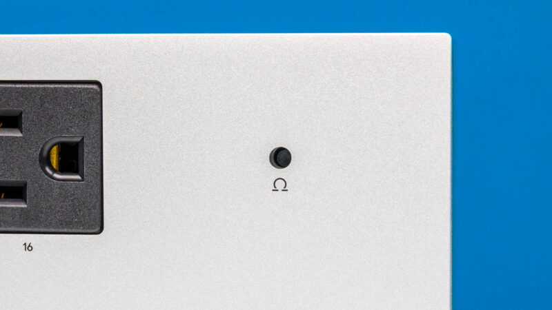
And above that all, we have the circuit breaker button, conveniently placed at the front of the PDU. Some PDUs have large breakers, but this is a smaller recessed button. We have not had to use this yet.
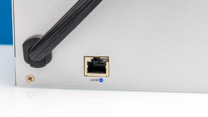
Around the rear, we find one more RJ45 Ethernet port, along with the PDU’s attached power cable.
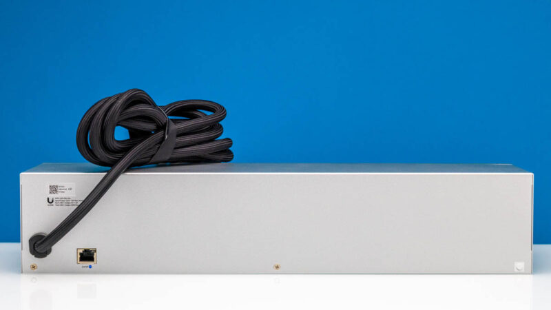
This final Ethernet port is similarly GbE-capable like the front ports. It feels like the other ports are there mostly for features we have not used (and are not in the basic installation steps.) We found an installation video from 2021 that said you would use this port 24 “ISP” port to go to your modem, then the two 1GbE ports on the other side are “Reserved for Virtual Router Redundancy Support Coming Soon”. These days, most will just use the 100M port on the front for management.
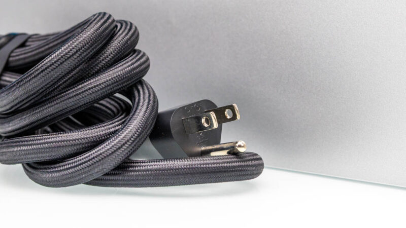
Meanwhile, the attached power cable features a typical NEMA 5-15 plug, alluding to the power limits of the device. Ubiquity has rated the USP-PDU-PRO to be able to handle a full 15A at 125V, distributing up to 1875 Watts – but it is not a PDU designed to plug into a higher voltage socket.
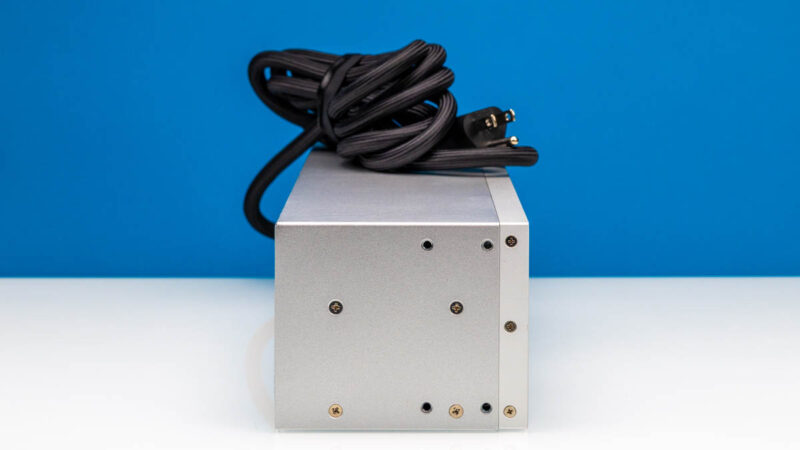
Finally, taking a quick look at the sides, we find a bunch of screws and screw holes for mounting, but nothing else of note.
Next, let us get inside and see how it is constructed.
Ubiquiti USP-PDU-PRO Internal Hardware Overview
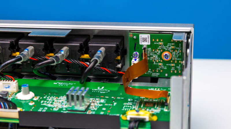
Cracking open the PDU, we get to what is arguably a more interesting sight. Between the networking hardware, the control hardware operating the PDU, and the ability to individually power cycle each and every power outlet, there is a lot going on inside to enable all of the functionality.
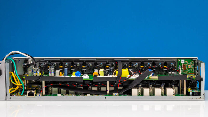
The PDU features two PCBs in layers. The lower PCB features the bulk of the actual power hardware, as well as the networking hardware. Meanwhile the top PCB primarily houses the smarts of the device, as well as the components that make up its 40W internal DC power supply.
Along the top here, we can see how the AC outlets are wired, with common neutral and ground wires running through the outlets. The individual black wires connected to each AC outlet are the hot (live) wires, and are individually controlled to allow each outlet to be power cycled as requested.
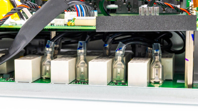
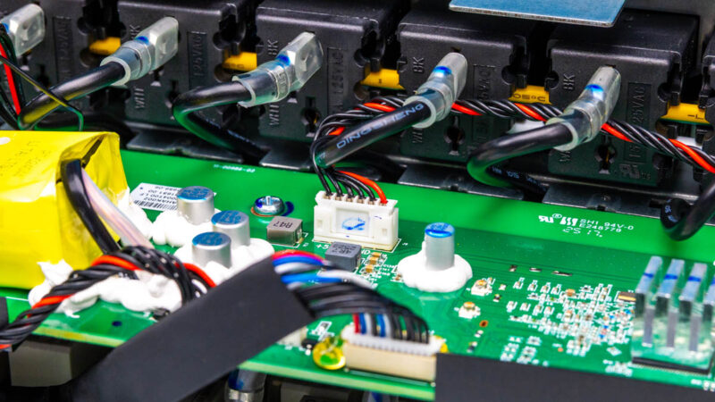
Going below deck, we can see the other end of those live wires, along with what appears to be a breaker next to each of them, likely to control the current flow. With 16 AC outlets, there are 16 of these breaker/wire pairs throughout the PDU.
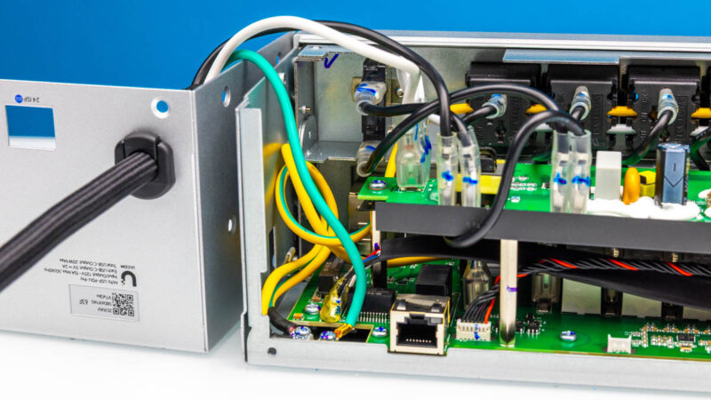
Along the top right corner, we find the USB-C port hardware. A small daughter board is connected back to the top layer PCB via a small ribbon cable, while power is provided via a separate cable coming in from a bit farther down.
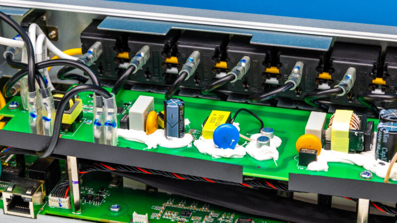
While we are up here, we find the DC power supply hardware in more detail, including the various capacitors and chokes needed to transform the power. Multiple cables lead to and from here, supplying power for the various smart bits of the PDU, such as the SoC and Ethernet jacks.
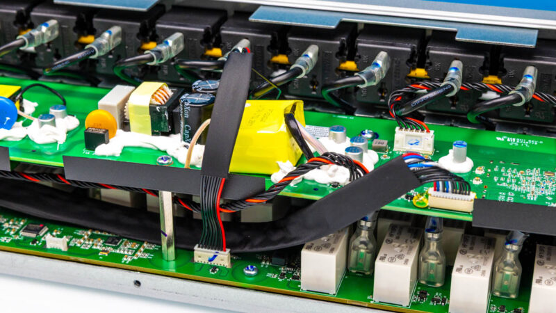
It is also hard to miss the significant amount of compound laid out around many of these discrete electrical components.
We usually just show what is inside, and we will let others debate the merits of the PDU’s construction since we are not a safety ratings agency.
Next, let us get to the software and management because this has a lot more going on than a simple power strip.
Ubiquiti USP-PDU-PRO Software Features
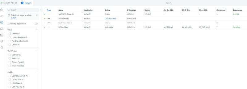
All of that relatively complex control hardware, in turn, exists to drive the software functionality of the USP-PDU-PRO. While it can be used with its tiny front-panel touch screen, the device is ultimately meant to be best controlled from a UniFi controller. Once you plug that 100M port in, and have a network path to the controller, it will show up in the UniFi application where you can click to adopt the PDU.
With multiple Ubiquiti devices, you can bring them together to manage them. One neat feature with this is that you can add power intelligence to the environment. A common one would be if a connected system fails ping checks for some time, you can have the port power cycle in the event that it was a hard lock on the device. That is a feature that has been around in PDUs for a long time, and it sometimes is a lifesaver. It can also yield funny reboot cycles if there is another issue.
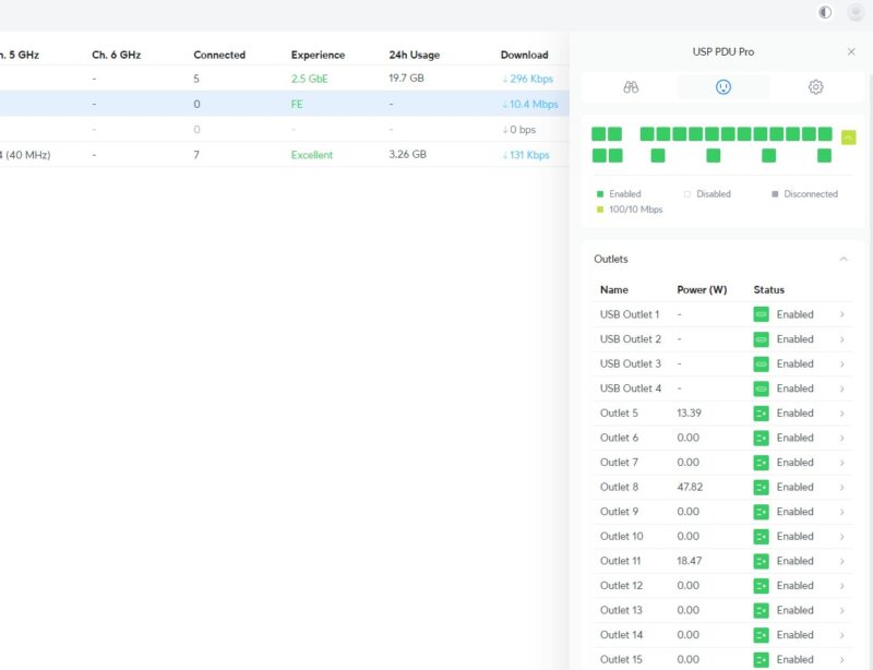
And once setup, Ubiquiti’s software can show the state of each individual port and outlet – both AC and USB. Information on the Ethernet ports is also available in this view.
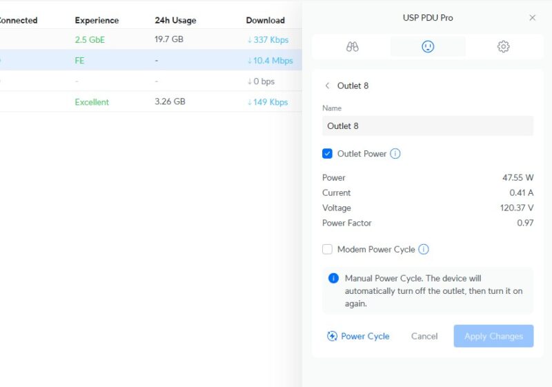
Diving deeper, the software can also provide information on and control over a single outlet/ port. In this case, showing us that Outlet 8 is drawing around 48 Watts of power. It is here that we can also power cycle the port. Along with the manual option, the USP-PDU-PRO also offers a “modem power cycle” option, which can automatically cycle a port (i.e. the modem) if the network connection drops, in an attempt to restore it.
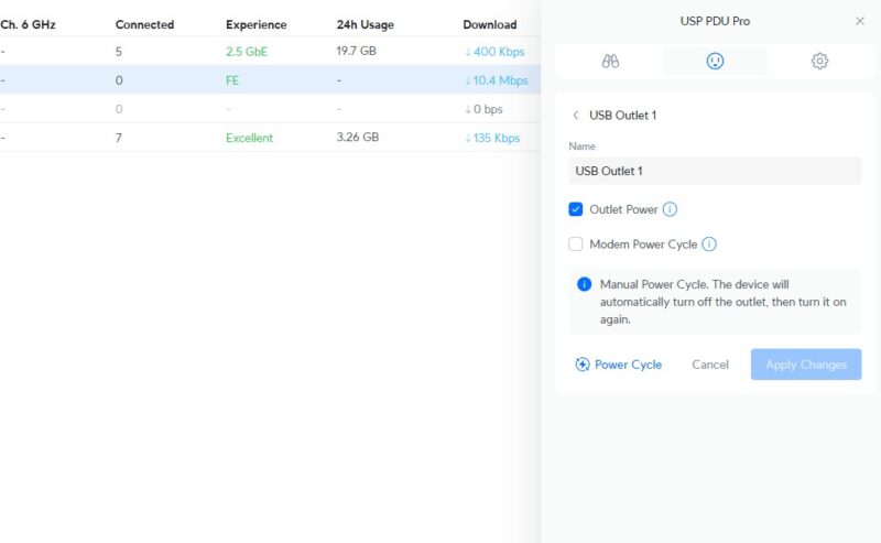
Unfortunately, the same power metrics are not available for the USB-C ports. They can still be cycled, but the device cannot show what an individual USB-C port is pulling.
If you are in a Ubiquiti UniFi ecosystem, this is much easier than trying to manage an APC PDU that has remote power cycle and per-PDU and per-outlet metering, plus managing firmware updates. Part of the premium of this device is the added intelligence and ease of use.
Final Words
The USP-PDU-PRO is a network-enabled PDU that is designed to slot into a stack of other Ubiquiti hardware. As a higher-end PDU, it features most of what you would expect from such a device, including individual outlet/port monitoring, remote access, and the ability to power cycle each port. While using it alongside other Ubiquiti products seems to be the best way to get the very most out of the PDU, it is not necessary to take advantage of the PDU’s core features.
STH has roughly 50 PDUs in the studio and the lab at this point (excluding any being tested and in the various colocation racks.) Those run equipment we are reviewing, but also run lights for the studio’s sets and so forth. We tried the PylePro PCO885 2U PDU around the same time that we got this. Those PylePro units are roughly one-third the cost since their control is essentially a single big switch. In the meantime, we have stopped using the PylePro and now have purchased 6 of these USP-PDU-Pro units. That is a good indication of the impression they made on the STH team.


From a rack perspective using AC, this unit is fine if you’re willing to sacrifice the rack space. Given how Ubiquiti is popular in SOHO and home labs, I can see this being popular and looks to fill that space nicely.
I’m disappointed in the USB-C ports only being able to provide 2A @ 5V as that is baseline USB charging. I’d love to find a PDU with multiple USB-C ports that could do 5A @ 19V which would be able to power multiple laptops or SFF systems in a rack. Bonus if such a PDU also provided metering and power switching on those same USB-C ports to force a reboot etc.
The ultimate device would combine USB-C PD up to 130W of power, USB KVM, and DP-alt more video switcher with MST support. Then have the optional feature per port of 2.5 Gbit USB based Ethernet interface combined with an internal Ethernet switch. This is a minimalist cabling schema of a single USB cable to fully support a cluster of SFF devices off of DC power.
I also would have liked to see a small embedded switch with PoE ports. Again, for the SOHO/home lab market, I’m certain there are a few installs that only need a handful of PoE enabled ports while the rest of the network would suffice with data only Ethernet. Or even have 90W PoE++ ports for the handful of gear that needs it while the everything else gets 30W off of a more affordable PoE+ switch.
As Kevin mentioned it would be nice to see USB-PD power …even just 65-90W would give enough to power a laptop or USB-KVM. It’s dream land I know, I don’t see any USB power on Eaton/APC..so kinda picking on Ubiquiti here. I don’t know that I want switching/poe power mixed into the PDU. Maybe a PoE++ injector, but mixing purpose isn’t great. If the USB power fails on this thing 5yrs from now you will still use it as a PDU – if the PoE injection fails you have to replace it as the gear downstream won’t work. Too many eggs in the basket. I do like the idea of having a simple 2 port switch on it to downstream to another PDU, but it feels unnecessary..if you need 3-4 of these in a rack you have a 1g switch for management anyway.
I’d rather see it be 1U with front and back power over the USB issues we might complain about. Even if it ends up being a “deeper” product in the rack that’s fine. 1U, 10″ deep or 2″ deep is still 1U taken up. 2U feels a waste. I frequently have 2x pdu’s: one on front of the rack matched with the same U on the back of the rack to keep as many U open for servers and switches as possible.
I specifically use Cyberpower 1U pdu’s over the eaton/apc options because they have plugs front and back. I consider Eaton and APC to have higher quality products in general, but I’d rather have more plugs and both sides, and for a simple PDU (un-metered, un-managed) it’s not rocket engineering. But split those between UPS’s to separate load on separate power units in the servers…green and blue tape on the power connectors to differentiate PSU to PDU to UPS.
I do like this PDU though, just the ability to label ports, centralized remote management on the same plane as the rest of the unifi gear. That’s pretty cool…I’ve got managed Eaton and APC that do the same thing, but it’s yet another system to connect to. Always a struggle to get that single pane of glass view.
I remember Ubiquti’s earlier mFi line and their mPower pro Ethernet-controlled power strips. So many firmware issues they abandoned the line and dropped support for the product.
Later, they introduced their USP line with the USP-Strip and USB-Plug products. Not killed off (yet) but also plagued with firmware and reliability issues.
Sometimes very nice hardware, often very poor software.
Weak , get a metered 240v 30A for $45 on Ali , and the price diff with ubiquity probably pays the 30A circuit instalation.
Have been using dataloggers pdu and have been super happy !!
Weak , get a metered 240v 30A for $45 on Ali , and the price diff with ubiquity probably pays the 30A circuit installation.
The eth ports are not worth , if PDU fails you should have plenty of alerts without the PDU reporting any more then LCD.
I agree with the others 65 watts of total power divided between USB-C and USB-A should have been standard.
Anyone try the PDU’s from Digital Loggers?
@Sam9 – I think you meant Digital Loggers? Which one did you use? Any issues?
> but it is not a PDU designed to plug into a higher voltage socket.
Of course not, it’s a 120 V PDU. Presumably you meant “higher current socket”, like a NEMA 5-20R or 5-30R.
> along with what appears to be a breaker next to each of them, likely to control the current flow.
The white boxes next to each outlet’s hot wire is almost certainly a relay, not a circuit breaker, allowing the power to be switched on/off per outlet. It may also contain the current transformer for measuring the current drawn from each outlet.
@franco Funny to see them mentioned here, I don’t think I’ve ever seen somebody else mention them. We’ve been quite happy with the digital logger EPCs, and particularly their support. They repaired (replaced?) a number of very old ones that had some sort of main board failure for us well outside of official support and eol, including building a custom firmware image for us to downgrade to at no cost – the API had changed greatly in the ~10 years since original purchase, and the source code was long lost for the system that talked to them…