
When looking to power devices using the same cables that provide data connections, PoE, or Power over Ethernet, is what you will most likely use. The explosion of IoT and connected devices mean that PoE switches are one of the fastest-growing segments in networking. You will often find three common labels for today’s PoE switches in the market: PoE switch, PoE+ switch, and PoE++ switch. Since we are doing more reviews of PoE products, we decided it would be a good time for a guide.
What Makes a PoE Switch “PoE”?
At first, PoE was designed to power low-power devices such as IP telephones. In 2003, IEEE 802.3af was standardized to use two of the four twisted pairs of wires in standard (at the time) Cat3 Ethernet wire runs. IEEE 802.3af provides up to 12.95W to powered devices at 37V-57V. There is some loss, so a PoE switch port is generally rated at 15.4W and between 44V-57V. You may also see this referred to as Type 1 PoE.
What Makes a PoE+ Switch “PoE+”?
Some switches utilize PoE+ which is an upgrade to the original 802.3af technology standardized as IEEE802.3at six years later in 2009. By then the industry had largely standardized on Cat5 wiring (or better) and many saw the need to power higher-end devices. As a result, a PoE+ powered device can use 25.5W at 42.5V-57V. A PoE+ switch port is rated at 30W and 50V-57V. Again, one has to account for potential loss. The standard still uses two pairs like PoE.
One of the key items to watch out for is that in a PoE+ switch, not all switch ports will be PoE+. One can have a mix of PoE and PoE+ ports. That is something to keep in mind when evaluating network switches. You may also see PoE+ referred to as Type 2 PoE.
What Makes a PoE++ Switch “PoE++”?
We saw approximately a six-year gap between PoE and PoE+, showing quick development. As one may expect, new generations of devices and endpoints such as faster Wi-Fi access points with higher power radio arrays and signal processors created a need for an even higher power standard. In 2018, we got the IEEE 802.3bt or PoE++ standard. PoE technology is now entrenched in the IT landscape. This landscape experiences growing demands for PoE. That and progression over the years is balanced by how much work is involved in a new standard. PoE++ is more complex in that there are two different types to 802.3bt. Predictably these are Type 3 and Type 4 PoE.
The differences between Type 3 and Type 4 are substantial. Type 3 can use either two wire pairs, like PoE and PoE+ or it can use four pairs like Type 4. Type 4 requires four pairs of wires. As one may imagine, the additional wires are to provide more power to devices.
PoE++ Type 3
A PoE++ Type 3 powered device can hit 51W at 42.5V-57V which is more wattage but the same voltage range as PoE+. A PoE++ Type 3 switch port is rated for 60W and 50-57V. Again here, the switch port voltage mirrors PoE+.
PoE++ Type 4
A PoE++ Type 4 powered device can hit 71W of supplied with power in the 41.1-57V range. The maximum switch port power is 100W in the 52-57V range.
As noted with PoE+, a switch may be advertised as a PoE++ switch even if not all ports are PoE++ capable. If you are looking at PoE++ switches you should, at minimum, check how many ports are PoE++ and what standard other ports use if any. You also need to check the type. Many switch vendors use “PoE++”, IEEE 802.3bt, Type 3 or Type 4, or simply state PoE and wattage which make this slightly harder to see.
Easy PoE vs PoE+ vs PoE++ Reference Chart
Along with the text above, we realized that many of our readers will want a handy chart to use. Here is an attempt at that with the basics:
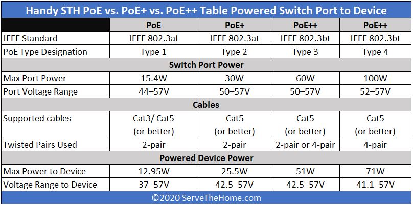
We set this chart up logically thinking from switch port or powered port (with a PoE injector) to the powered device. The above includes input power to the device where there will be a loss as well so devices tend to use less power than input power just like a server or workstation.
A Few Notable PoE Switch Items
In terms of PoE switches, the above are the basic numbers. There is a lot more to it than just per-port numbers. As an example, PoE switches often oversubscribe the total PoE capacity of a switch with more ports. This makes sense since many devices use less than maximum power. As a result, just because you have a switch with all PoE++ Type 4 ports does not mean you can use all of them at maximum load 24×7.
This is such a big industry trend that PoE switches have a lot of handy features. For example, many can remotely power cycle ports. This is great if, for example, you need to remotely power cycle an IP camera. Other switches have per-port monitoring and can even include fault detection to help identify if there are issues in the wiring to the device. PoE is a multi-billion dollar ecosystem that has a long legacy so tooling is good and constantly getting better.
Final Words
Hopefully, this helps level set some of the PoE, PoE+, and PoE++ labels along with the Type 1, Type 2, Type 3, and Type 4 labels STH uses. We focused on the IEEE standards here. As one can imagine, with the nine or so year gap between PoE+ and PoE++ we saw some proprietary standards appear. Still, for most of our readers, we focus on the IEEE industry standards since those are most common to encounter both on the switch and on the device side.
We review PoE switches here so we did not venture into PoE injector discussions. You may encounter “PD” and “PSE” in documentation. “PD” is for powered device. These are the endpoints such as IP phones, cameras, and wireless APs. “PSE” is power sourcing equipment. At STH, we primarily will review PoE switches but one can also use non-PoE switches and devices such as PoE injectors to introduce power over Ethernet runs. We are using PoE switch ports here as our “PSE” but there are other options out there.


The thing that excited me about the standard were the changes is signature detection, and “Maintain Power Signature” (MPS).
i.e. for smart lighting and other applications where you want/will have low idle power consumption.
Cat 5 came out in 1995
@Timc, yeah, but this article here is about PoE. How and why would that little factoid be relevant with regard to PoE?
> Type 4 requires four pairs of wires
Cat.5e and cat.6 have four twisted pairs. If the “type 4” uses **all** for pairs… how one sends data? Or the same wires are used as power lines (low frequency) and data lines (high frequency) simultaneously? And then a consumer device, connected to to PoE++ switch, has to divide those stuff?
Yes, same wires for data and power.
Congrats. You completely left out communication speeds affected by the different types of poe. Article is incomplete.
We’ve been using UPoE (Cisco’s PoE++ variant) for years and it didn’t change speeds. We have low power servers now even powered with PoE++ and speeds are the same. Or are you just trolling?
Really?? Trolling, admin, get a clue… Why not mention the different speeds for the standards? People might want to know they’re limited to 100Base T with 802.3af.
@IndustrialAIAdmin A lot of early 802.3af gear used 100 Mbit networking with the power provided on the unused pairs. This forced a choice between PoE and bandwidth. Note that that era is over a decade old now with 802.3at switching being the defacto standard for PoE and 802.3bt just arriving to market.
Also formally 2.5/5/10 Gbit speeds are not supported under 802.3at as they should be 802.3bt strictly adhering to the spec. However, this is more of a formality since 802.3at already supports power and data over the same pins, just these ‘non standard’ implementations adhere to the higher data standard.
FYI, POE uses DC power, and AC for signals.
@Mitch the way you could use all 4 pairs for data and power is because data is an AC signal and power is a DC signal. For the purpose of this discussion assume the data signal needs a 1 volt peak to peak to differentiate between a 0 and a 1, and power is provided at 10 volts. By having the signal fluctuate between 10 and 11 volts peak to peak, you can now deliver both power and data over the same pair. This is commonly done in RF applications, for instance to send power over a coax cable to a signal repeater in a cable TV system.
Is Cisco’s UPoE switch (SG350X series for example) able to power 802.3bt type3 devices or not? It would be great if the v2 of the article could include that standard as well as maybe ubnt’s/mikrotik’s passive PoE. Nevertheless, good informative article as always.
I was looking for total output of PoE++ with single or dual power supplies. Following the simple formula:
Watts=Amp X voltage
Example: W= 20Amp X 120 Volt
Can such a switch support 2400 W total per switch?
Comments are closed.