
We bought a cheap Centec-based ZX530S-24S2CQ switch that we are reviewing as a generic switch. This is a 26-port Ethernet switch with twenty-four SFP+ 10G and two QSFP28 100G ports that can also run at other speeds. We purchased our review unit on AliExpress for just under $575, and multiple vendors sell similar units usually in the $480-600 range. It might be cheap, but the question is whether it will be any good. We ask because it uses a Centec CTC7132 switch chip. Allegedly, this is a 6th-generation switch chip from the company, but we have not seen it in our lab before and we have not seen a thorough online test of it. It seems to be more focused on sales in its domestic Chinese market. So, of course, we had to buy one (and another switch with the same chip) to see how it performs. The exact seller no longer sells the switch, but several are available online with model names that match the switch PCB’s silkscreened model. If you are wondering whether we found something interesting, the answer is yes… yes we did.
As a quick note, the video was sponsored by Micro Center.
Centec ZX530S-24S2CQ External Overview
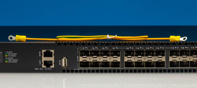
The front face places the management interfaces at the left edge and the data-plane port field across the rest of the panel. This first view shows the complete layout, including the LED status legend that runs along the top of the chassis.
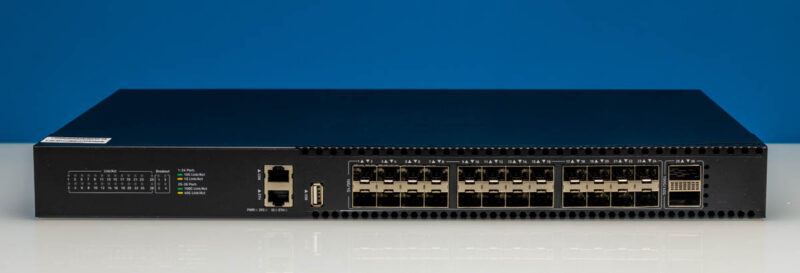
From this angle, we can see how the port field is organized. The SFP+ cages dominate the faceplate, with the two larger uplink cages set apart at the right edge.
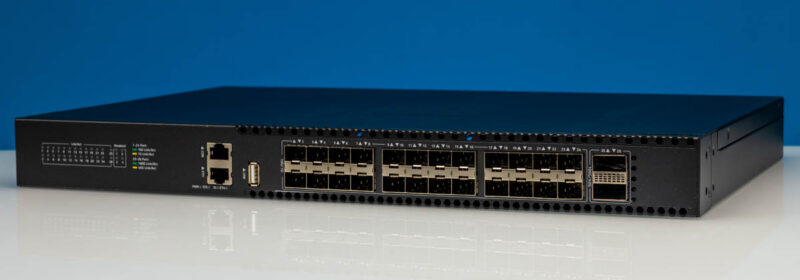
The left side of the panel holds the management cluster. This angled view shows the console and Ethernet ports alongside the USB-A connector that sits between them and the first SFP+ cage.
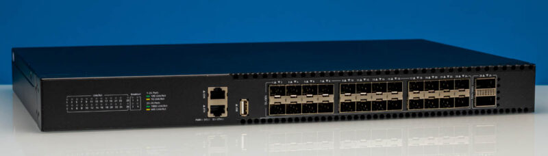
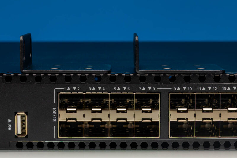
Two loose L-shaped rack brackets with empty mounting holes are supplied for standard 19-inch racks, resting on top of the chassis in our photographs rather than fastened to it. The left data-plane section here shows the paired SFP+ cages labeled for 10G or 1G operation.
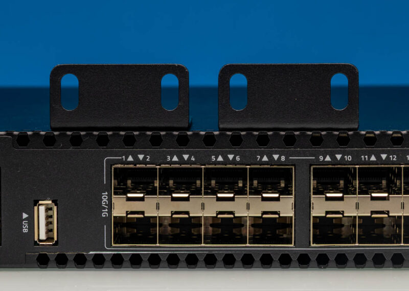
The same bracket pair appears again from a closer angle. This view also makes clear that the port numbering starts at the left edge of the SFP+ bank, with ports arranged in vertical pairs across the panel.
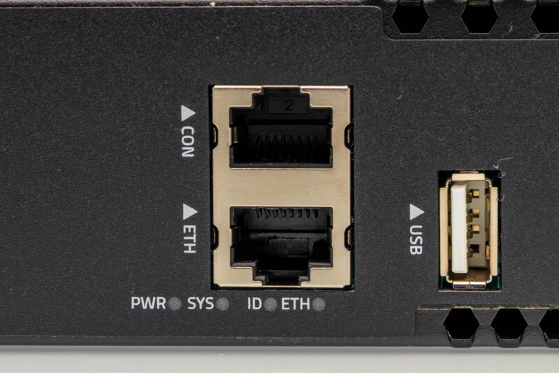
The management cluster contains a stacked CON and ETH RJ45 pair, status LEDs for power, system, ID and Ethernet, and a USB-A port. The separate ETH jack provides out-of-band access independent of the data plane, while the CONSOLE port serves local serial configuration.
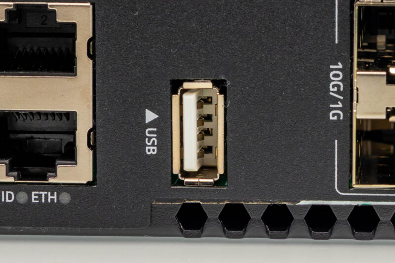
This macro view shows the USB Type-A port positioned between the management RJ45 pair and the SFP+ cage bank. The triangle icon above it marks the connector clearly on a panel that is otherwise dense with ports.
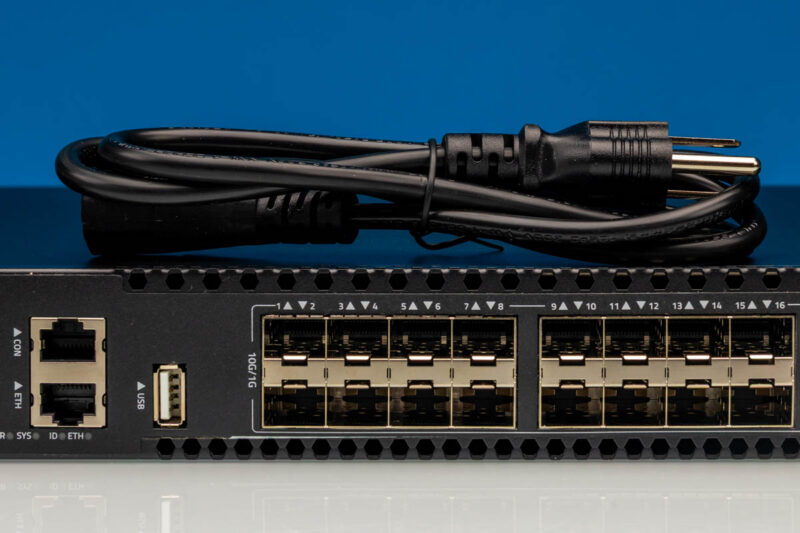
The included AC power cord rests across the chassis in this front view. This gives a sense of scale for the 1U form factor alongside the management ports and the start of the SFP+ bank.
A yellow looped wire with ring terminals sits along the top edge here, likely intended as a grounding strap. The panel labels for CONSOLE, ETH, USB and the speed indicators are all visible in this view.
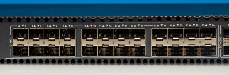
The main data field contains twenty-four SFP+ cages arranged as paired positions and labeled for 10G or 1G operation. This close-up shows ports numbered 1 through 24 across the bank, with the pairing marks printed above each pair of cages.
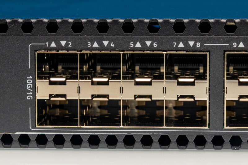
This detail view covers the left section of the SFP+ bank, showing ports 1 through 8. The 10G/1G label on the left edge applies to this entire group of twenty-four cages.
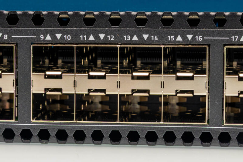
The middle section continues with ports 9 through 16 in the same paired arrangement. This consistent layout makes cable management straightforward since each vertical pair shares a common center line.
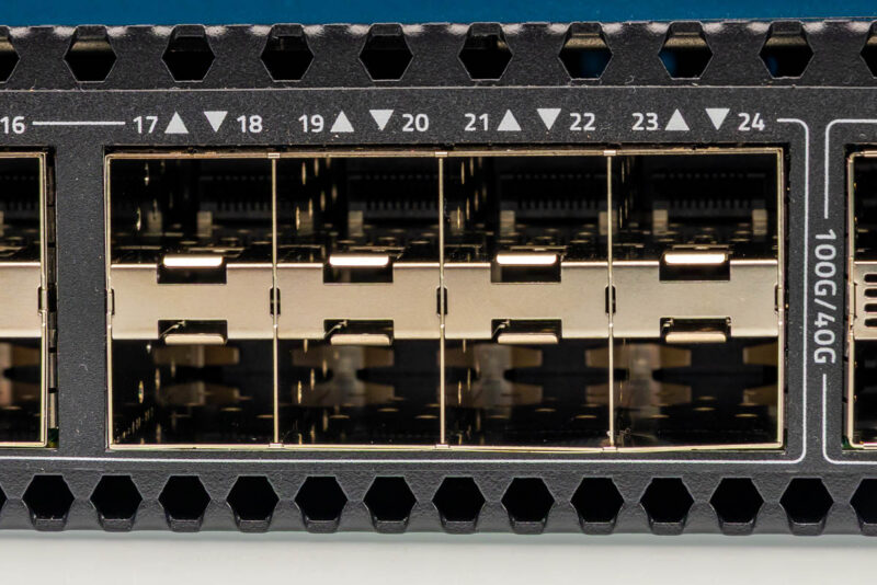
This close-up shows ports 17 through 24 at the right end of the SFP+ bank, with the vertical 100G/40G text visible on the right edge marking where the larger cages begin.
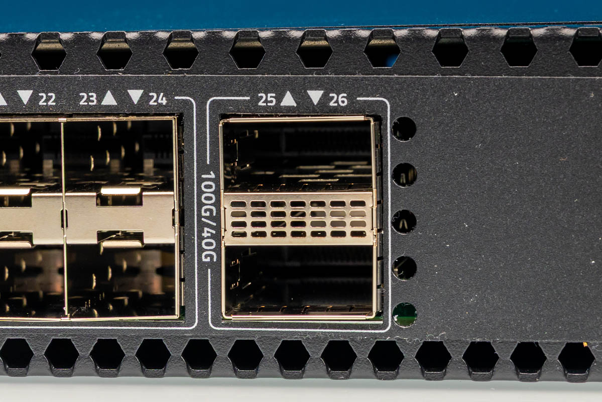
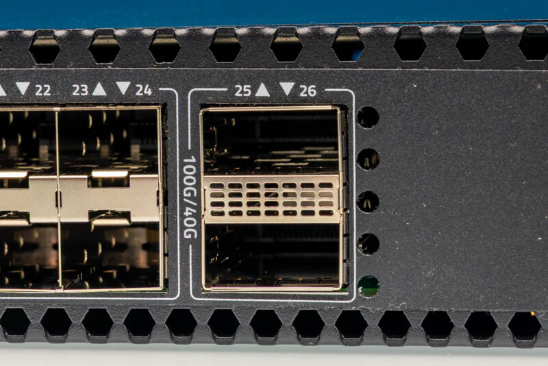
At the right edge, two vertical cages are marked for 25 and 26, labeled with a vertical 100G/40G legend. In the benchmark they were used as 100G links with RS-FEC. These larger form-factor ports provide uplink capacity distinct from the SFP+ bank.
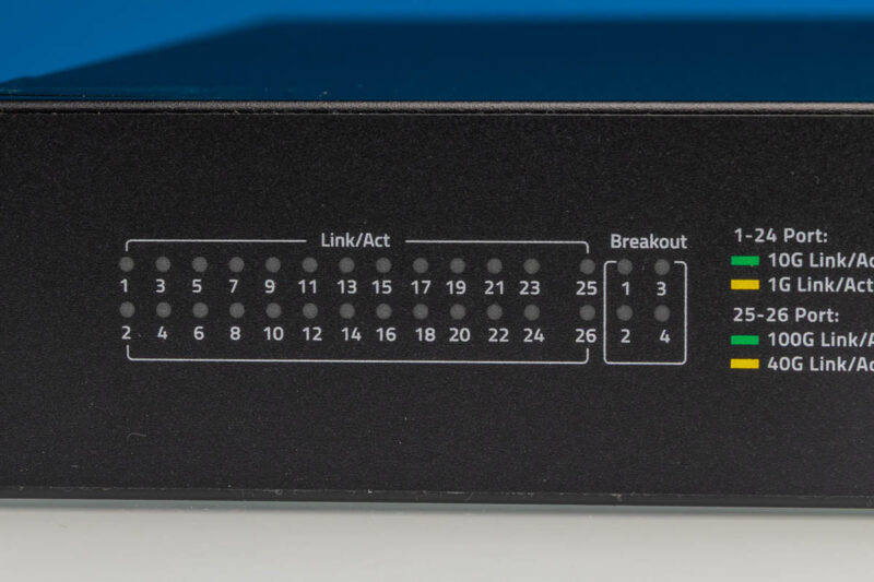
The indicator panel separates per-port Link/Act positions for all twenty-six ports from a separate Breakout group, with color legends distinguishing speed classes. That layout helps administrators identify which LEDs correspond to normal port activity versus the upper-speed cage indicators.
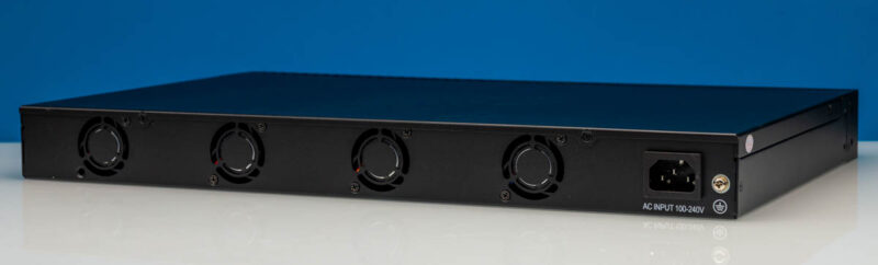
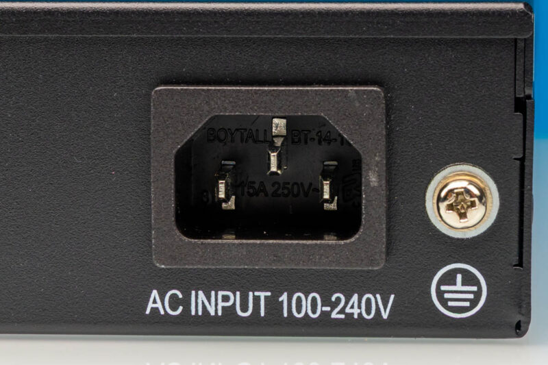
Moving to the rear of the chassis, we find four cooling fans and an IEC C14 power inlet labeled AC INPUT 100-240V. A threaded metal fitting sits beside the inlet next to a ground symbol, providing a bonding point for the chassis.
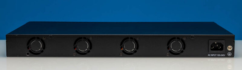
This angled view shows the same rear panel from the side, giving a better sense of how the four fan grilles occupy most of the back plane with the power inlet at one end.
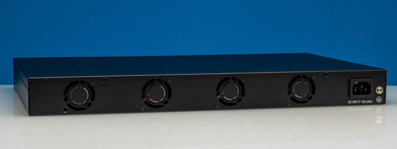
From this higher angle, we can see the top edge of the chassis alongside the fans and power input. The rear panel carries four fan grilles, with no additional venting visible along the side face.
This macro shot of the AC input socket shows internal markings including BOYTALL BT-14-1 text and an adjacent grounding screw. The C14 inlet accepts a standard IEC power cord, so no special cabling is required for installation.
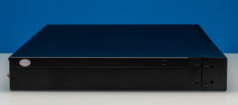
The side profile shows mounting holes on the front bracket area. These provide attachment points for the included rack ears.
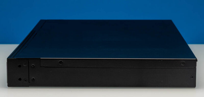
This side view reveals a red circular QC PASS sticker near the left edge, two vertical columns of small mounting holes on the right panel, and a gold-colored threaded connector protruding from the far left. The chassis is otherwise solid metal with no additional venting along this face.
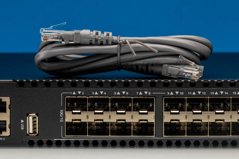
A gray Ethernet patch cord rests on top of the front panel in this close-up. The clear RJ45 connectors are visible alongside the SFP+ cages labeled 10G/1G and the USB-A port, showing one way administrators would connect management or data links to this switch.
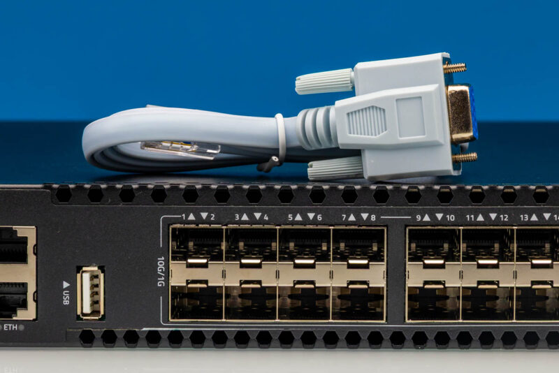
This second cable accessory has a D-sub style connector with thumbscrews at one end. That connector form is commonly used for console access on networking equipment, complementing the RJ45 CONSOLE port on the front panel.
The external design is straightforward and functional for a low-cost 26-port switch. The front panel clearly separates the management cluster from the data-plane ports, with the two larger uplink cages set apart at the right edge. We appreciate that CentecOS labels the port speeds directly on the faceplate, which simplifies cable planning in a dense rack. The included accessories are minimal but adequate: two L-shaped rack brackets and both console and Ethernet cables for initial setup.
Next, let us get inside the switch.