
As part of our reference series, before we get into a new set of content, we wanted to quickly show the difference between QSFP and QSFP-DD modules. While in the era of QSFP, QSFP+, and QSFP28 generations of standards moved more slowly and were easier to understand, the new generation of optics and networking, perhaps starting with the 400G generation and beyond, is quickly becoming more complex.
QSFP Versus QSFP-DD Here Are the Key Differences
Perhaps the biggest difference between the two types of optics is the electrical connectivity side. Here you can see the QSFP28 100G optic on the left, and the QSFP-DD 400G optic on the right. Notice that the QSFP-DD has more connection pads for more connectivity.
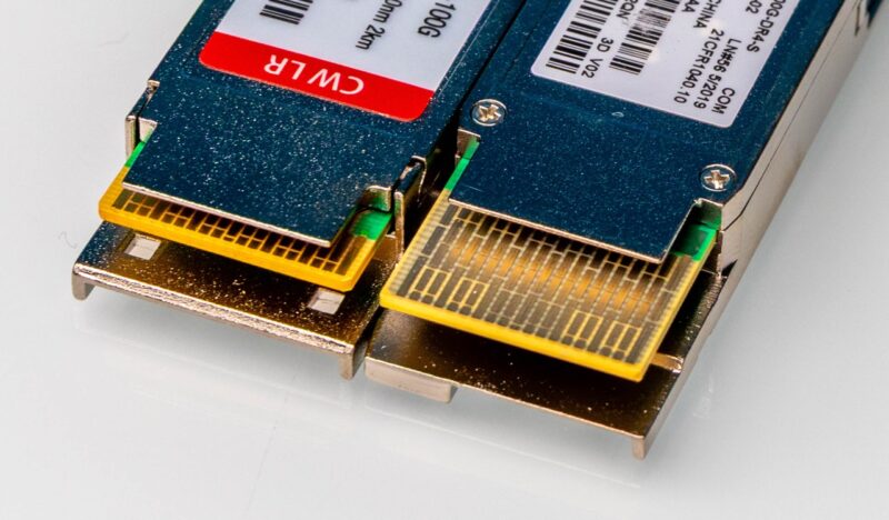
QSFP28 and QSFP56 use four electrical lanes. For example, if you have QSFP28 and have four 28G lanes (25G) then you have 4x 25G or a 100Gbps optic. QSFP56 doubles that to 56G or 50Gbps per lane making it 4x 50G or a 200Gbps standard.
QSFP-DD, in contrast has eight electrical lanes that are enabled by that second row of pads on the connector.
When we get to 400Gbps optics, this matters a lot. With QSFP56-DD (56/50G per lane) we have 8x 50G for 400Gbps. If we had QSFP28-DD (28/25G per lane) we would have 8x 25G for 200Gbps. If we only had four lanes, at those same speeds 50G would give us 4x 50G or 200Gbps.
The option to step up to 400Gbps lanes in QSFP modules means using QSFP112, or 112Gbps lanes. While that may sound easy, many devices only have 56G PAM4 SerDes because 112G SerDes are much faster and newer.
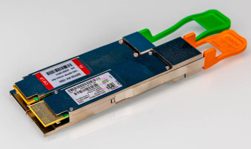
You may also notice that the QSFP-DD connector is longer but the outer cage demensions are similar. That is why the QSFP optics can be plugged into QSFP-DD cages.
Backward Compatibility
There is some backward compatibility with QSFP and QSFP-DD. QSFP-DD was designed in such a way that you should be able to plug QSFP devices into QSFP-DD cages and have them work. The reverse is not true, however, since plugging QSFP-DD devices with more electrical connections and a longer connector into a QSFP cage with fewer connections would not work.
Final Words
With optical modules, it is often helpful to think of them in three parts:
- Form factor (QSFP, QSFP-DD, OSFP)
- Electrical connectivity configuration
- Optical connectivity configuration
This guide focused on the form factor and electrical connectivity since inside the modules gearboxes can be used in the path of the electrical-optical connectivity. Still, these are foundational and important concepts that folks need to learn when moving to higher-speed networking. At 400G and higher speeds, there are many more boxes that need to be thoughtfully checked as you are designing solutions.


It also might be useful to illustrate how this differs on the host connection end. For instance, compare the QSFP+ from TE part number 2110819-1 with the QSFP-DD from TE part number 2318579-1. The “2110819 F2 Product Drawing” and “2318579 A Product Drawing” links available on these parts’ Digikey pages or direct from TE’s site show how the socket and PCB footprint work for each connector option.