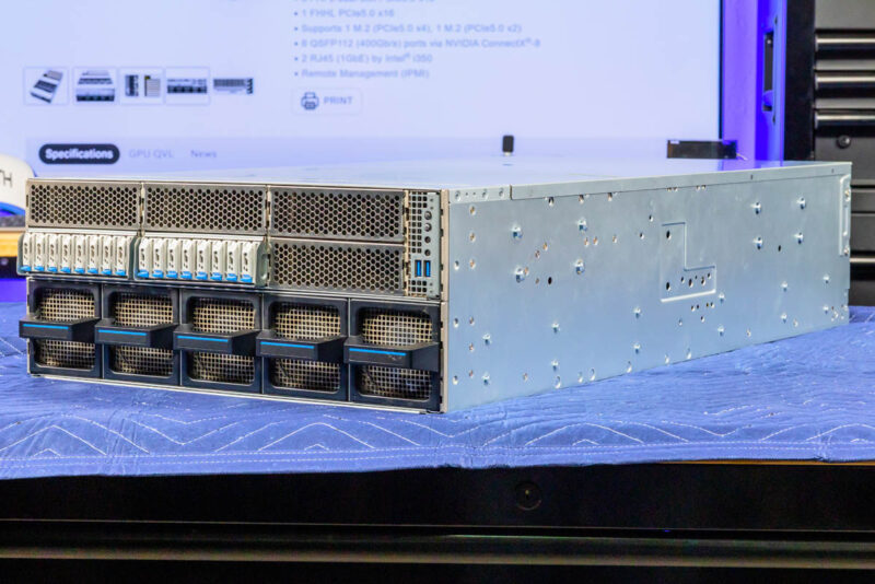
ASRock Rack 4UXGM-GNR2 CX8 Internal Hardware Overview
We are going to generally move from the front behind the storage and front fans to the rear of the system.
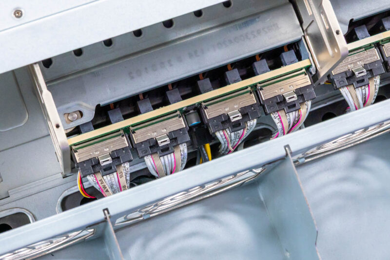
First, we have the storage backplane. You can see here that the E1.S SSDs have MCIO x8 connectors, with two drives serviced per cable and connector.
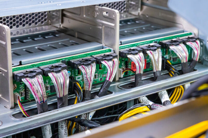
Here is another look at this, and also why the E1.S drives make a lot of sense in a high-airflow design like this.
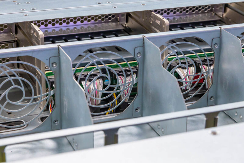
Behind the storage backplane is the top fan partition with five fan modules.
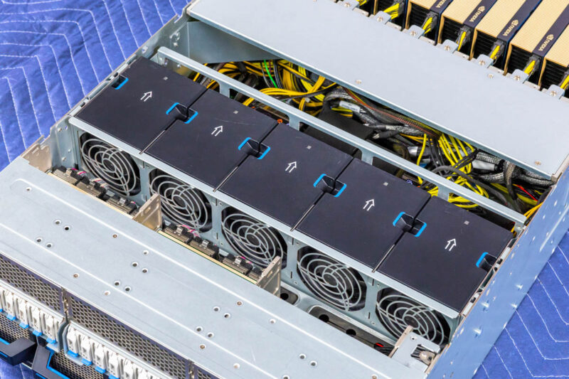
If you recall, the front of the chassis had five fan modules on the bottom 2U. These are the five fan modules for the top 2U.
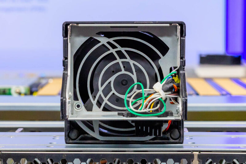
Here is a quick look at the fan module.
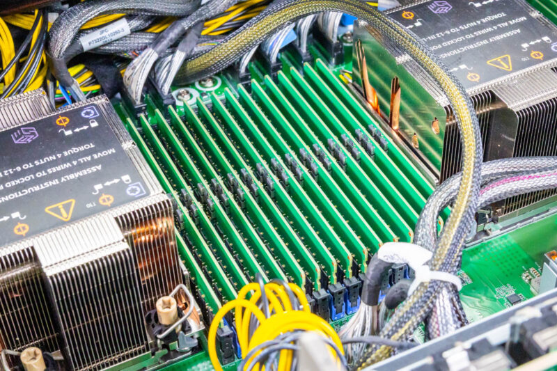
You can remove the fan partition, and that is where you find the motherboard, the CPUs, and the memory.
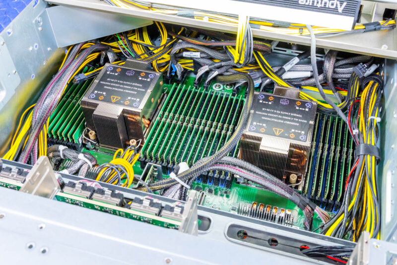
In here we have dual Intel Socket E2 or LGA4710 sockets. That means we can use Intel Xeon 6 CPUs, either 6700E, 6700P, or 6500P. Using E-cores is less common in these servers, and given the GPU and memory content, we expect to see Intel Xeon 6700P CPUs as those are the higher-end Granite Rapids P-core parts.
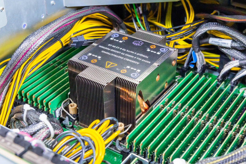
Another benefit of the Intel Xeon 6700P series is that each processor has eight channels of DDR5 and can run in 2-DPC (2 DIMMs per channel) mode. That means we get a total of 16 DIMMs per CPU and 32 DIMM slots in the system. Memory support depends on the CPU, but the major benefit is being able to handle more RAM.
The board also has a vertical DC-SCM module.
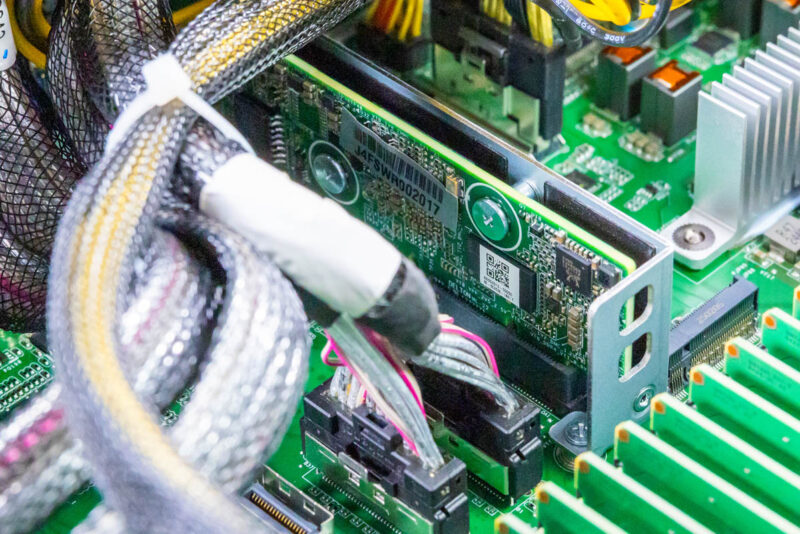
You can also see one of the internal M.2 slots and many of the front MCIO connectors.
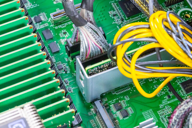
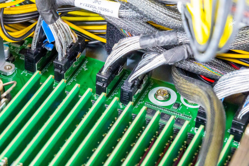
If it looks like there are lots of MCIO and power cables, that is exactly what you are seeing. Instead of having traditional slots for risers, ASRock Rack has a number of MCIO connectors that it can use to connect the SSDs and the NICs in the system.
Behind the CPUs and memory, we get to the GPU area. Here you can see the tray that helps with airflow and keeps the GPUs installed during shipping. It also provides space for the PCIe GPU power cables to run.
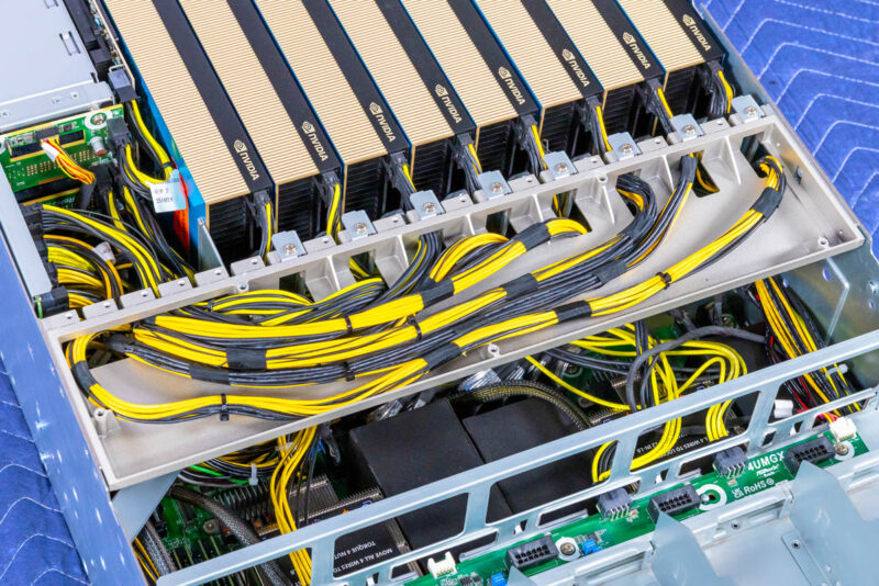
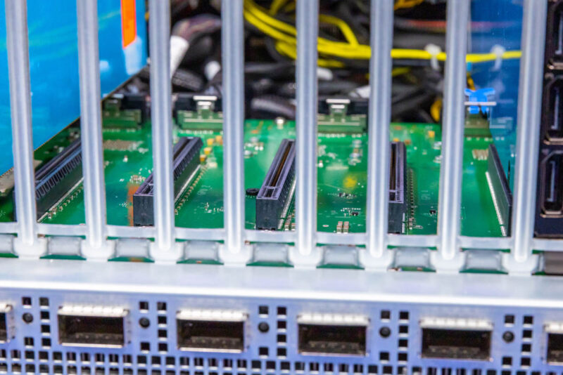
If we pull our four of the GPUs, you can see the configuration here. There are MCIO cables connecting the NVIDIA ConnectX-8 PCIe switch board to the motherboard. Between those and the PCIe slots, you can see where the ConnectX-8 packages are mounted on the other side of the PCB.
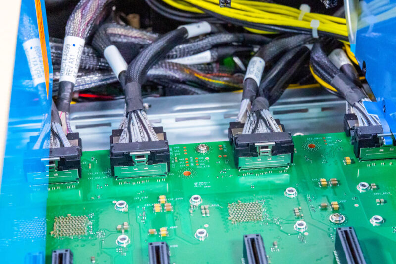
Each ConnectX-8 connects to the host system via a PCIe Gen5 x16 connection. Then there are two PCIe Gen5 x16 slots. We have been told these are actually designed for PCIe Gen6, but we only have PCIe Gen5 GPUs at this point.
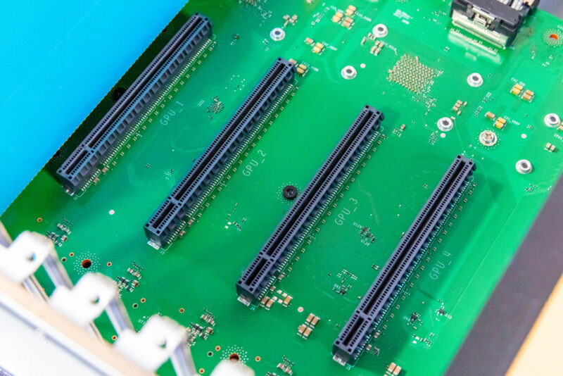
Normally, in this view, you would see large PCIe switches, often with 144 lanes. Instead of having two of those and then multiple NICs, the NICs have the PCIe switch integrated, which can lower the cost of the system and also help with power consumption by removing two big packages.
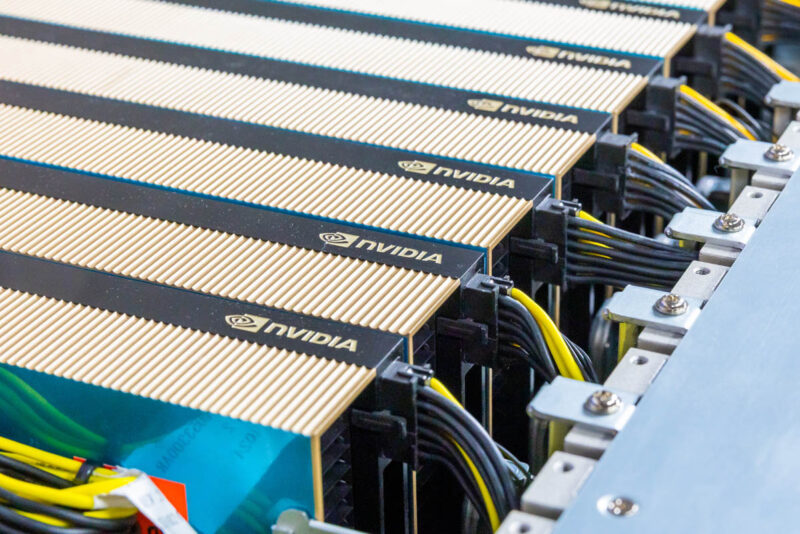
Of course, the star of the interior is also the eight NVIDIA RTX Pro 6000 Blackwell Server Edition GPUs. Each needs its own power connection, but these are passively cooled cards. If you recall the top fan partition with 2U fans, that is what is used to cool this area.
You can also see the NVIDIA BlueField-3 DPU between the PSUs and the GPUs.
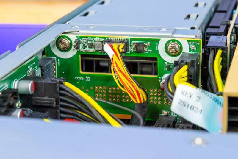
Behind the power supplies is a power distribution board that helps get power from the four PSUs to the rest of the system.
Next, let us discuss the topology in more detail.


It looks like the storage backplane blocks airflow. If this is true, how are the SSDs cooled?
I think not anyone will connect 32 monitors to the 32 display ports in this system. So what is the purpose of so many display ports?
None of the DP outputs may be used if the cards are utilized for virtualization or AI workloads.
The cards have DP outputs because they could also be used in desktops or workstations and they also share the same PCB as their actively cooled variants, NV just did away with the fans, but decided to keep the same ports as the other versions.
You could, of course, also hook up a giant video wall, but I don’t think this is the right system for that purpose.
If I’m understanding this correctly, the GPUs are not directly used by the server? They’re just powered by the chassis and goes through the 400Gb link to the switch, which then goes back to the server? So you could have a rack full of these, and expose ~80x GPUs to a single 1U system? (Or more likely, a SLURM setup?)