
When we first saw the Gigabyte G242-Z10 at SC19, we thought it would appeal to a number of our readers. This is a four GPU, 2U server powered by an AMD EPYC 7002 series “Rome” CPU. It also has a number of physical innovations that make it more flexible than many other systems we have seen. At STH, we have reviewed 1U 4x GPU systems previously. By moving to a 2U form factor, Gigabyte can handle a higher-TDP CPU with up to 64 cores. It can also offer more storage and expansion options in a shorter-depth chassis. In our review, we tried a number of different configuration options to probe this flexibility.
This system is even more profound. We know that the US Department of Energy in announcing its first three Exascale systems has focused on a four GPU to one CPU node design using future AMD Infinity Architecture. Both the 1.5 Exaflop Frontier Supercomputer and 2 Exaflop El Capitan will use nodes designed with the same ratio of CPU to GPU, using AMD EPYC, as the Gigabyte G242-Z10. There are future technology advancements that will further this design that the exascale systems will utilize, but it, at minimum, validates this type of model and ratio going forward.
Gigabyte G242-Z10 Overview
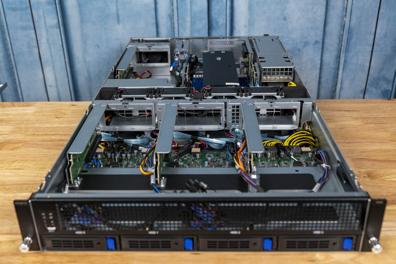
We are going to take a look at the Gigabyte G242-Z10 starting from the front and moving to the rear of the unit. Overall, it is a 2U server with only four 3.5″ front panel hot-swap bays. The rest of the server’s front is dedicated to a large grill to provide maximum airflow to the GPUs inside.
Quickly, on the front of the chassis, we find fairly standard features such as a power button, ID button, and activity lights. We also see a USB 3.0 port. Many GPU servers have dropped front panel USB, so this is a nice feature if you need it for your data center operations.
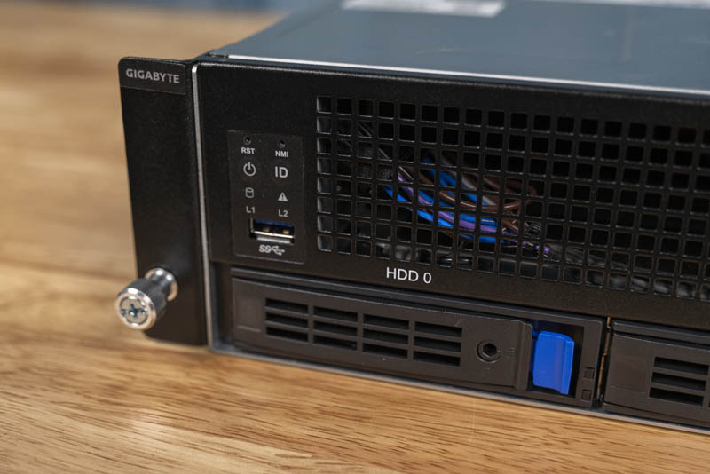
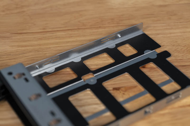
The four 3.5″ hard drive slots are unremarkable, except for a feature: tool-less 3.5″ drive trays. One places a drive into the tray, aligning screw holes with pins on the drive tray. One then simply collapses the drive tray so the pins secure the drive. 3.5″ drives are often used in servers like these to hold video such as surveillance video staging for GPU processing. These tool-less drive trays can save several minutes per server for drive installation and replacement. Here is a tray open.
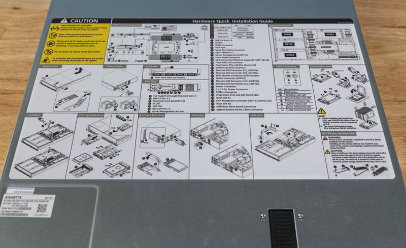
Another nice usability feature is the top-cover Hardware Quick Installation Guide. Gigabyte is doing a great job adding these to its servers much like large OEMs such as Dell EMC and HPE. These guides help data center staff locate and understand areas they may be asked to service.
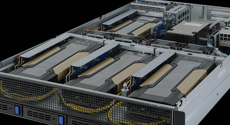
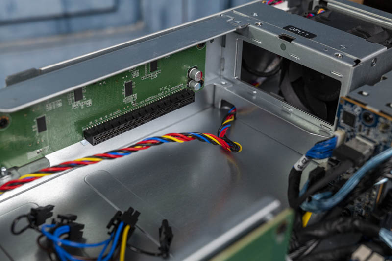
Perhaps the biggest feature of this server are its quad PCIe x16 dual-width internal GPU slots. The server is custom-built for this exact purpose. Three of the GPU slots sit at the front of the chassis and are fed power by a PCB just below the GPUs.
A common use-case will be with dual-width GPUs such as the NVIDIA Tesla V100S and AMD Radeon Instinct MI60. We used NVIDIA GeForce RTX 2080 and 2080 Ti blower-style GPUs. We also tried some more exotic cards such as the Intel Visual Compute Accelerator and AMD Radeon Vega Frontier Edition. Dual slot cards either passively cooled or blower-style work extremely well in this server. You can configure the server for either Tesla (server) or GeForce (desktop) GPU power options.
We wanted to go a step further in our testing and try something beyond the dual-width cards. We configured the server as well with a set of Tesla T4’s. There are two reasons for this. First, having 16GB of memory per GPU means one has more memory than with GeForce RTX 2080 Ti’s which can sometimes cause trouble for server UEFI. Second, there are quite a few systems that can cool dual width GPUs but fail with single-width cards. Now that we have a set of four Tesla T4’s in the lab, we figured we need to get them into this four GPU server.
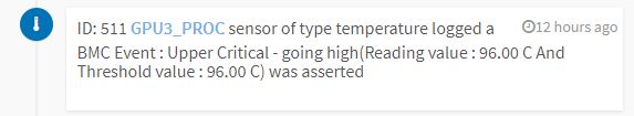
While the firmware generally worked fine (except that we needed to disable network boot ROM on the QLogic quad 25GbE card we used), cooling was more challenging. We saw temps with the Tesla T4’s climb up to 96C in one case.
Temperatures for dual width cards were held in-check without issue which we expect in a system like this. Single width cards need a blanking spot above the card. Adding this expansion slot blank brought temperatures to what we would expect. Most will not use these with Tesla T4 GPUs, however, we wanted to let our readers and the VAR community know that if you do set this up, there is a quick $2 fix to be able to use single-width GPUs, AI accelerators, and FPGAs with this system.
You will also notice that the expansion slot I/O for these GPUs is internal so you cannot use the GPU display outputs on GeForce or Quadro cards in this system.
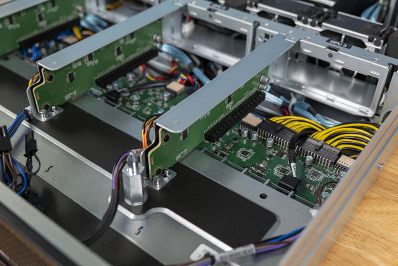
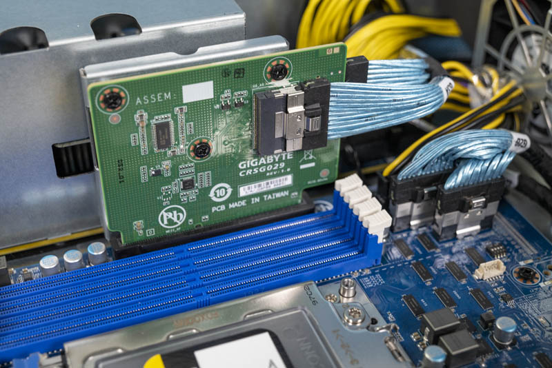
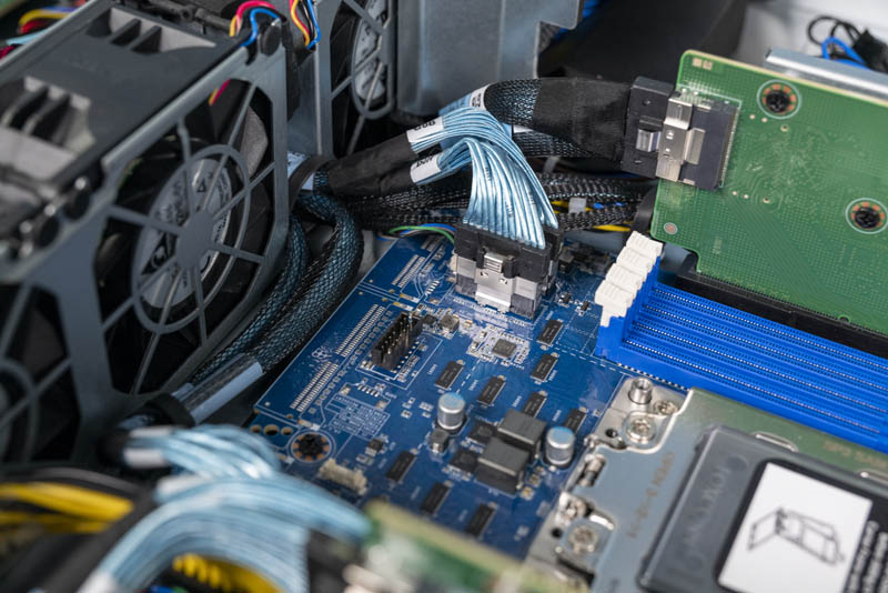
The risers that the GPUs are on are actually extremely interesting. Many systems have PCB that extends to the front GPUs. A riser is then mated to the motherboard plane PCB in a process that can be cumbersome. Gigabyte instead cabled the GPU risers. That both aids in PCIe signal integrity as well as makes installation easier. Instead of unscrewing the GPU riser, installing the GPU, then having to mate the assembly into a riser slot, one simply puts the GPU in this riser and screws the assembly into the chassis. No riser mating is required. This may not seem like a big deal, but if you have worked with 1U 4x GPU servers previously, you will immediately understand the appeal. This is a little touch but saves perhaps a minute or two per GPU for installation.
The fourth of the PCIe Gen3 x16 slots is next to the motherboard in the rear of the chassis. This slot is in many ways similar to the first in terms of function.
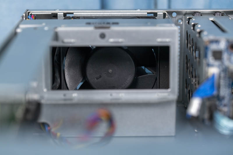
One major difference with this GPU spot is that it has an extra fan in the rear. With two GPUs in-line from the front of the chassis to the rear along the left side, Gigabyte is forcing more air through the second GPU to keep it cool.
On the topic of fans, along with that rear fan, there are four mid-chassis fans. These heavy-duty Delta fans are secured by rubber pins but are not hot-swappable. Recently we discussed this topic in Are Hot-Swap Fans in Servers Still Required.

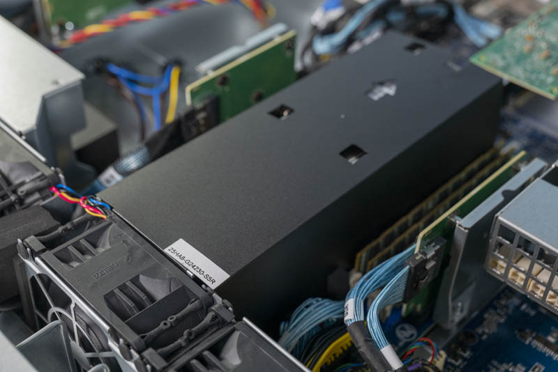
Another aspect of this design is around CPU cooling. Gigabyte uses an airflow guide to keep air moving over the CPU. This airflow guide only pulls air from a single fan which means this is not a redundant cooling setup. This lack of cooling redundancy is being done to lower costs and makes sense for many GPU server deployments. We also would like to see Gigabyte innovate on the air shroud design with a sturdier hard plastic unit.
At the heard of the system is an AMD EPYC CPU and eight DIMMs. The choice of AMD EPYC processor here is important. By utilizing AMD, Gigabyte was able to make this a single-socket system rather than a dual-socket system. Further, AMD sells discounted “P” series EPYC Rome SKUs that are less expensive than their dual-socket counterparts. This system is designed to provide a lot of performance while minimizing the cost overhead and moving from two Intel Xeon CPUs to one discounted AMD EPYC “P” series processor can have an enormous TCO impact.
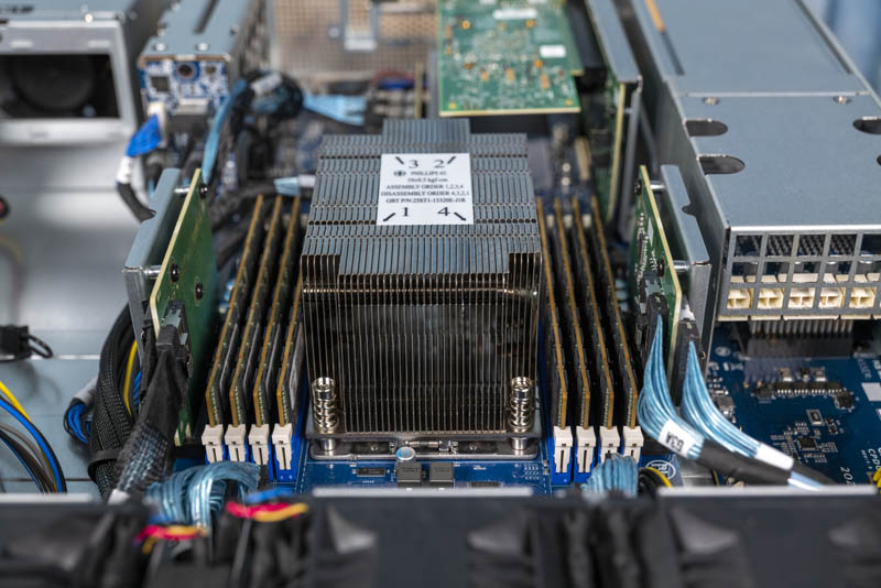
This is a 1 DIMM per channel configuration so one can use up to 2TB of memory. The EPYC 7002 series can use up to 8 DIMM channels in 2 DIMMs per channel mode for 16 DIMMs or 4TB of capacity. Here, we see half of that in order to prioritize space in the server for GPUs.
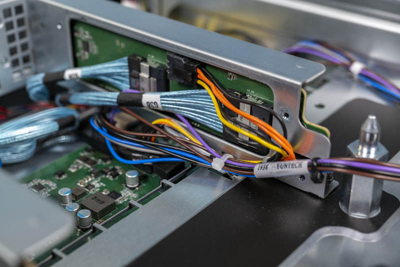
Along the side of the DIMMs, one will notice two risers. These are used for features such as providing PCIe lanes to the front panel GPUs.
Keen readers may have noticed this, but the motherboard itself is analogous to a half-width 2U4N server node. Gigabyte has made modifications such as you can see the mid-plane connectors have been de-populated (see our Gigabyte H262-Z62 Review for a 2U4N server node comparison.) This is a very innovative idea especially given the challenge of creating a GPU server with this layout.
Another example of this is that you can see a higher-density rear PCIe expansion card slot connector. The riser itself supports PCIe x16 lanes either in x16 and x0 or x8 and x8 configurations. If you are using a 100GbE or even a quad 25GbE NIC as PCIe x16 networking, the x8 slot below is not used. Alternatively, if you have PCIe x8 cards such as 40GbE or 50GbE cards, you can use both slots as x8 slots.
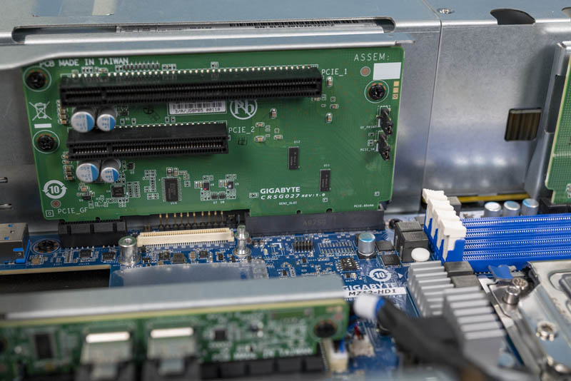
Just below that is an OCP 2.0 NIC slot. We like that Gigabyte is using industry-standard OCP NIC form factors in their servers.
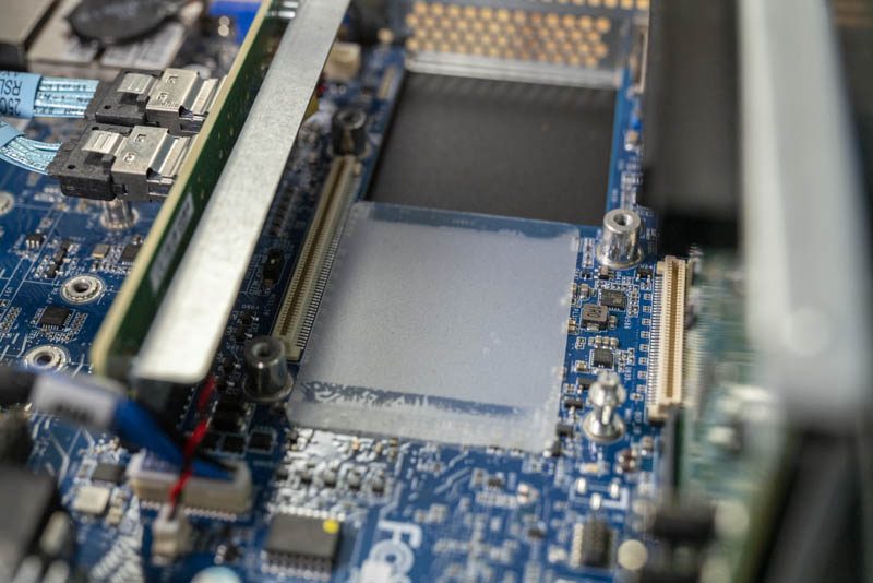
At the middle-rear of the PCB, we have a few interesting features. You can see mounting points for two M.2 slots. There is actually only one M.2 NVMe slot populated. It supports M.2 drives ranging from 42mm to 110mm or M.2 2242, 2260, 2280, and 22110 sizes. If you use that slot, you are limited to 180W TDP AMD EPYC CPUs.
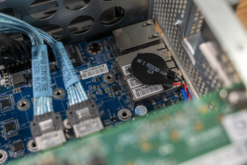
We normally do not focus on CR2032 batteries in our reviews, but this is going to be an exception. Since the motherboard is so dense, Gigabyte has the battery wired and affixed to the two 1GbE ports. The above photo shows the challenge this provides as all three MAC addresses and two of the MAC address barcodes are obscured. We are using a PVT sample here and this is something that Gigabyte can fairly easily mote elsewhere in the system. We hope they do move this.
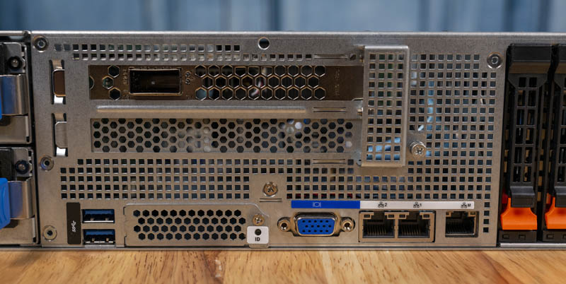
Looking at the rear of the chassis, we can see a “wild” layout for a modern 2U server. Very few servers have IO, PSUs, drive bays and even a fan at the rear, but the Gigabyte G242-Z10 includes all of these features.
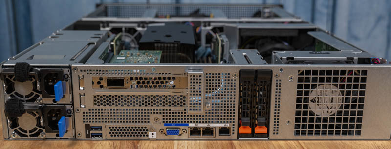
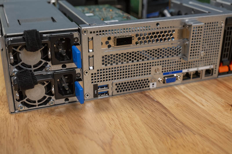
The left side of this view looks fairly normal. We have two stacked redundant power supplies along with features such as the OCP NIC slot and two riser slots above. You can see the QSFP28 NIC port in the top PCIe x16 riser slot we mentioned earlier.
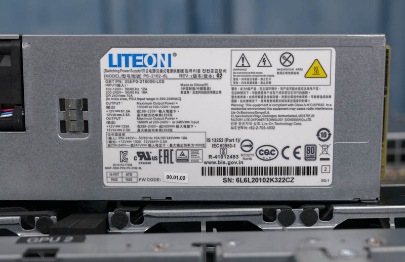
The power supplies are nice LiteOn 1.6KW 80Plus Platinum units.
Rear I/O beyond the risers consists of two USB 3.0 ports and a VGA port for local KVM access. There are two 1GbE NIC ports powered by an Intel i350 NIC which is a popular 1GbE option. One also has an out-of-band management port that can be used to manage the server. We are going to go over the management options later in this article.
An extremely nice feature we have in this chassis is two rear 2.5″ NVMe/ SATA drive bays. With the above-noted restriction when populating the M.2 slot on using up to 180W TDP CPUs, the rear bays for NVMe storage make a lot of sense in this machine.
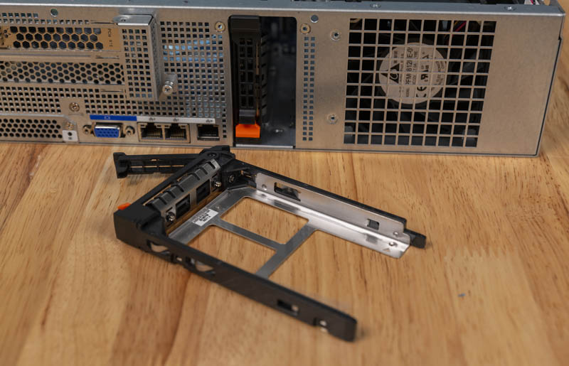
One will again note that this is a tool-less drive tray. It is great to see Gigabyte working to get its customers and partners tool-less trays which save a lot of time when configuring and servicing systems.
Perhaps the most interesting facet of this server is simply the number of PCB elements involved. In many servers, there is a motherboard PCB, maybe a riser PCB or two, and then a front hot-swap bay PCB. Here, there are more than a dozen individual PCBs used to make this server. It is certainly an interesting case study in modular server design. Overall, this is a very unique package that many of STH’s readers will want to take a look at for their GPU compute clusters.
Next, we are going to get to the system topology and management before moving onto our performance benchmarks.


Thanks for being at least a little critical in your recent reviews like this one. I feel like too many sites say everything’s perfect. Here you’re pushing and finding covered labels and single width GPU cooling. Keep up the work STH
As its using less than the total power of a single PSU, does this then mean you can actually have true redundancy set for the PSUs?
Also, I could have sworn that I saw pictures of this server model (maybe from a different manufacturer) that had non-blower type GTX/RTX desktop GPUs installed (maybe because of the large space above the GPUs). I dont suppose you tried any of these (as they run higher clock speeds)?
https://www.asrockrack.com/photo/2U4G-EPYC-2T-1(L).jpg
https://www.asrockrack.com/general/productdetail.asp?Model=2U4G-EPYC-2T#Specifications
I am looking forward to see similar servers with PCIe 4.0!
Been waiting for a server like this ever since Rome was released. Gonna see about getting one for our office!
For my application I need display output from one of the GPUs. Can not even the rear GPU be made to let me plug-in a display?
To Vlad: check the G482-Z51 (rev. 100)
Has anyone tried using Quadra or Geforce GPUs with this server? They aren’t on the QVL list, but they are explicitly described in the review and can be specc’d out on some system builders websites.