
The Supermicro X10DRG-Q is a motherboard with a purpose: provide a platform for many PCIe accelerator cards. Supermicro has been making similar boards for several platform generations. A typical purchaser of these motherboards are those who need Tesla, Xeon Phi or GPU compute platforms. As such, it is a motherboard and platform we have wanted to test for years. Today we get that chance with the dual Intel Xeon E5-2600 V3 offering.
Test Configuration
As we will see, the Supermicro X10DRG-Q has a few features which warrant a few test configuration tweaks compared to our normal setup.
- CPU: 2x Intel Xeon E5-2690 V3
- Motherboard: Supermicro X10DRG-Q
- Memory: 8x SK. Hynix 16GB DDR4 2133MHz ECC RDIMMs
- PCIe cards: 2x Xeon Phi 31S1P, 2x NVIDIA K4000, Mellanox ConnectX-3 FDR VPI Infiniband/ 40GbE
- SSD: 3x SanDisk CloudSpeed 1000E 800GB SATA, 3x Intel S3700 100GB
- Operating Systems: Ubuntu 14.04 LTS, Windows Server 2012 R2, VMware ESXi 5.5, CentOS 6.5
Overall, we needed to change our configuration slightly for this motherboard and utilized a Supermicro SYS-7048GR-TR as our test bed.
The Supermicro X10DRG-Q
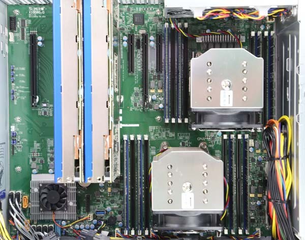
Upon unboxing the Supermicro X10DRG-Q, one can tell it is something different. The motherboard measures 15.2″ x 13.2″ in order to give the motherboard enough space for add-in slots. The top portion of the motherboard near the dual LGA2011-3 sockets looks much like a standard dual socket motherboard. The expansion slot area shows why the motherboard is special. We are using a Supermicro SC747TQ-R1620B chassis to house the X10DRG-Q due to its size, and highly recommend that purchasers of the motherboard do the same.
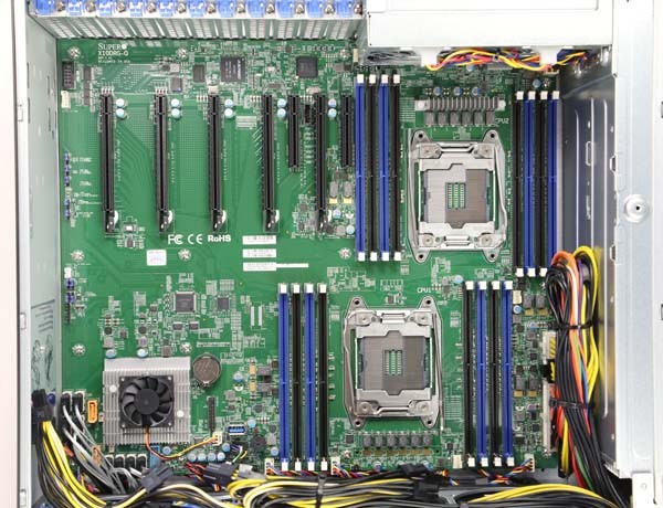
As one can see each socket has eight DDR4 RDIMM slots which can be filled with up to 1TB of memory between the 16 slots. The CPU sockets are offset which helps cool hotter processors. As with any PCIe compute platform, great cooling is essential. One should note that the heatsink mounts are a narrow ILM design. See our guide on narrow versus square ILMs to understand the differences. Since both layouts have been available for years, this is something to keep in mind when configuring a solution.
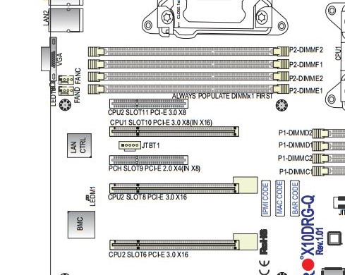
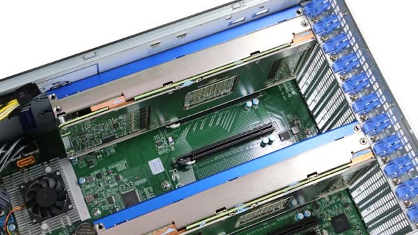
Getting to the big selling point of the motherboard, the PCIe expansion slot layout is nothing short of impressive. One can see that there are five PCIe x16 physical slots and two PCIe x8 physical slots. Each PCIe x16 slot is two slots away from the next which is important for double width add-in cards. Four of the slots are PCIe 3.0 x16 electrical which provides the data connectivity for larger cards. One of the PCIe x16 physical slots and one of the x8 physical slots are PCIe 3.0 x8 electrical. The final PCIe x8 slot is a PCIe 2.0 x4 electrical slot. The bottom line here is that there are 64x PCIe 3.0 lanes dedicated for the four bottom PCIe x16 slots. This configuration yields 4-way NVIDIA SLI support. The top two slots are PCIe 3.0 x8 electrical. This is one of the few or only platforms that expose a full 80 PCIe 3.0 lanes to users for expansion card customization. One, of course, requires two Intel Xeon E5 V3 series processors to support all 80 lanes (40 per processor.)
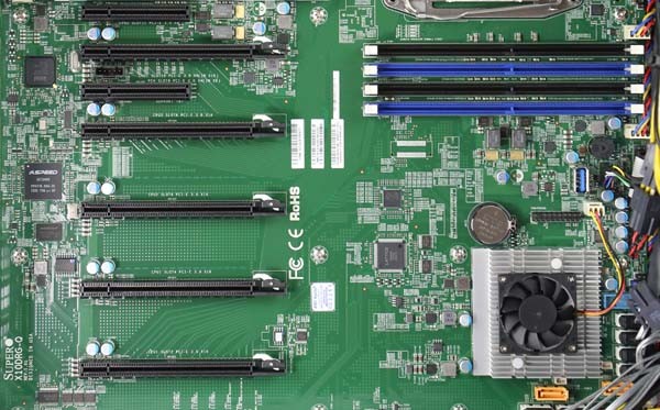
The PCIe 2.0 x4 (in a x8) slot has another feature: Thunderbolt support. Supermicro has an add-in card (AOC) dedicated to supporting Thunderbolt support. The small five pin header above the PCIe 2.0 slot is a header for the Thunderbolt ports.
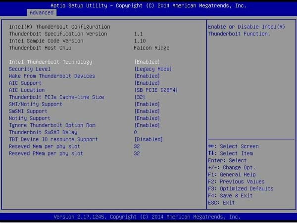
The motherboard’s BIOS has built-in support for Thunderbolt as well.
We took a pair of Intel Xeon Phi 31S1P cards to show off how the spacing practically works. One can see that the cards fit perfectly and do not cover another PCIe slot as they would in a standard motherboard. The cards slot below the DDR4 DIMM slots and leave the three top slots open for PCIe based storage or networking.
One differentiation point for the motherboard is the bottom PCIe x16 slot. There is a double width slot on the X10DRG-Q. The PCB below this slot is relatively bare, so having a double slot PCIe card in the bottom position will not cover up many critical headers like it would on other motherboards.
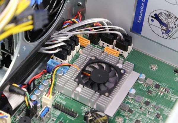
Moving on, Supermicro utilizes the onboard Intel C612 PCH SATA III ports. There are 10x SATA 6.0gbps ports. Two of the ports have connectors for SATADOM modules. Along this edge there is also a USB 3.0 front panel header and an internal Type-A USB 3.0 header. That provides the USB connectivity one would need in most situations. These headers are located relatively far from the PCIe slots which is a nod to the intended application of the motherboard.
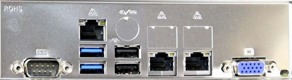
Moving to the rear panel, we see a very standard Supermicro rear I/O layout. This does help if one ever needs to replace the I/O shield. There is a legacy serial and VGA port flanking the other ports. The two blue colored USB ports are USB 3.0. Atop the USB 3.0 ports there is a Realtek controlled IPMI LAN management port. Additionally, there are two USB 2.0 ports for peripherals or USB storage. The two gigabit network ports are controlled by an Intel i350 Ethernet controller. The i350 is a higher quality/ cost part than the Intel i210 NICs that lower cost solutions have onboard.
Overall the Supermicro X10DRG-Q is built for one purpose: housing many PCIe expansion cards. Whether that is four fast NVIDIA GPUs for 4-way SLI or four Tesla/ Intel Xeon Phi cards, the Supermicro X10DRG-Q is equipped to handle high powered systems.
Thermal Results
To capture these images we utilize our FLIR Ex series professional thermal imaging camera and turn on FLIR’s MSX enhancements so we can see components outlined clearly. We put the system under 100% CPU load for a period of 24 hours to let “heat soak” set in prior to taking the images.

Even after a full day of fully utilizing the processors, the highest recorded temperature was 44.8C, which is very cool. One can see that there are very few components sitting in front of the four PCIe 3.0 x16 slots. As a result, the Supermciro X10DRG-Q has a well optimized cooling layout for installing four large GPUs or MICs.
Supermicro Management
Supermicro’s IPMI and KVM-over-IP as described a few times on this site, allows for a lot of deployment flexibility. Things such as fan speeds, chassis intrusion sensors, thermal sensors, and etc. can be monitored remotely. Alerts can be setup to notify the admins of issues. Beyond this, the functionality also allows for remote power control. You can do remote power up, power down, and reset of the server in the event that it becomes unresponsive. In fact, the test system has never had a keyboard, mouse, CD/DVD ROM, or monitor hooked up to it, even after multiple BIOS tweaks and operating system/ hypervisor installations.
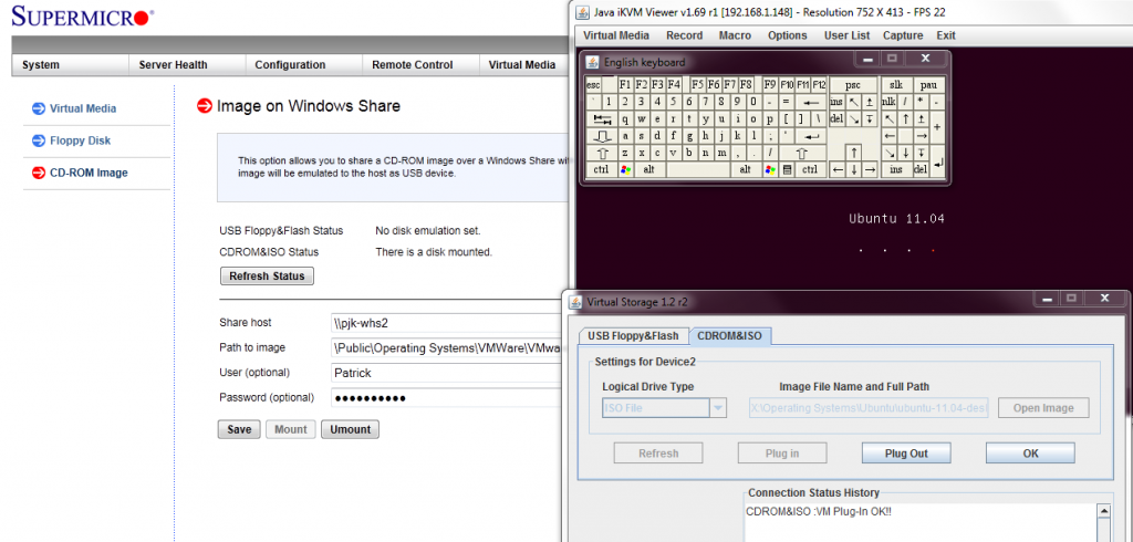
Another important feature is the ability to remotely mount CD images and floppy images to the machine over the dedicated management Ethernet controller. This keeps maintenance traffic off of the primary Intel NICs. At the same time it removes the need for an optical disk to be connected to the Supermicro motherboard.
The latest revision of Supermicro’s BIOS has a great feature: the BMC IP address shows up on the post screen! This is a super feature because if one has a KVM cart hooked up to the system, it gives an indicator of which machine one is connected to during post.

Supermicro does include KVM-over-IP functionality with the motherboard. We have been testing servers from HP, Dell, Lenovo and Intel that all required an additional add-in key to get this functionality. It is an absolute time and money saver in the datacenter and other vendors should follow Supermicro’s lead in this space.
Conclusion
We have been wanting to take one of Supermicro’s GPU compute platforms out for a spin and the Supermicro X10DRG-Q certainly exceeded our expectations. The platform booted up the first time in every configuration we tried. Mellanox FDR Infiniband cards, 40GbE Intel Fortville cards, RAID controllers, Xeon Phi’s, NVIDIA Quadro cards we tested all booted without issue. For those seeking a quad Xeon Phi or quad Tesla/ Quadro solution, the Supermicro X10DRG-Q should be atop lists.


I got the same system you were using for the test and am geting a USB audio solution too. I’m excited for the build.
Can you say ultimate Horizon View vSGA VDI box?
I am curious, why in the overview photo of the X10DRG-Q motherboard and consistent with the photograph of the motherboard supplied in the Supermicro user manual (MNL-1677), dated 04 Feb 2015, is there no similar heat sink mounted to the 6 phase VRM group supplying CPU1 (right)?
The 6 phase VRM group for CPU1 with the purposefully intended heat sink, removed, most likely operating outside of the engineered designed parameter and as such, perhaps less than prudent configuration for extended use.
Unlike like the VRM heat sink for the 6 phase group supplying CPU2 (left), did the VRM heat sink for CPU1 (right) physically interfere with the mounting of the factory recommended heat sink and associated cooling fan combination for CPU1?
Should that be the case, the VRM heat sink for CPU1 was removed to physically make room for the CPU cooling fan attached to the heat sink for CPU1, then:
i) Did not, the cooling fan for CPU1 block the temperature measuring FLIR camera’s visual line of sight (LOS) in the supplied test image and review?
ii) Since the FLIR camera is not able to see beneath the masking cpu cooling fan (opaque object), could not have measured the temperature of the non thermally sinked VRM group for CPU1.
iii) What is the nominal anticipated temperature for CPU1’s VRM group, scaled for a 135W, E5 2690v3 cpu?
iv) What was the contacted (Pt sensor) measured temperature of the VRMs supplying CPU1 after 24 hours of use?
To reiterate, the blocked visual line of sight for the FLIR camera, implying that the temperature data for the VRM’s supplying CPU1, was not measured and per this report, still an unknown.
Permitting such non heat sinked VRMs, more than likely resulting in higher operating temperatures with component cooling rate properties that are now much less than idea, perhaps leading to reduced product longevity and worthy of further engineering design considerations, when using such CPU heat sink/cooling fan combination.
Park McGraw
I am curious, why in the overview photo of the X10DRG-Q motherboard and consistent with the photograph of the motherboard supplied in the Supermicro user manual (MNL-1677), dated 04 Feb 2015, is there no similar heat sink mounted to the 6 phase VRM group supplying CPU1 (right)?
The 6 phase VRM group for CPU1 with the purposefully intended heat sink, removed, most likely operating outside of the engineered designed parameter and as such, perhaps less than prudent configuration for extended use.
Unlike the VRM heat sink for the 6 phase group supplying CPU2 (left), did the VRM heat sink for CPU1 (right) physically interfere with the mounting of the factory recommended heat sink/cooling fan combination for CPU1?
Should that be the case, the VRM heat sink for CPU1 was removed to physically make room for the CPU’s heat sink cooling fan, then:
i) Did not, the cooling fan for CPU1 block the temperature measuring FLIR camera’s visual line of sight (LOS) in the supplied test image and review?
ii) Since the FLIR camera is not able to see beneath the masking cpu cooling fan (opaque object), could not have measured the temperature of the non thermally sinked VRM group for CPU1.
iii) What is the nominal anticipated temperature for CPU1’s VRM group, scaled for a 135W, E5 2690v3 cpu?
iv) What was the contacted (Pt sensor) measured temperature of the VRMs supplying CPU1 after 24 hours of use?
To reiterate, the blocked visual line of sight for the FLIR camera, implying that the temperature data for the VRM’s supplying CPU1, was not measured and per this report, still an unknown.
Permitting such non heat sinked VRMs, more than likely resulting in higher operating temperatures with component cooling rate properties that are less than idea, perhaps leading to reduced product longevity and worthy of further engineering design considerations, when using such CPU heat sink/cooling fan combination.
Park McGraw
Less in error, the removal of my technical inquires, a questionable act at best and impinging behavior upon the credibility of Servethehome and its author.
Thus, I shall repost the following (revised) comments pertaining to this motherboard review.
—————–
I am curious, why in the overview photo of the X10DRG-Q motherboard and consistent with the photograph of the motherboard supplied in the Supermicro user manual (MNL-1677), dated 04 Feb 2015, is there no similar heat sink mounted to the 6 phase VRM FET group supplying CPU1 (right)?
The 6 phase VRM FETs for CPU1, with what appears to be the marked location of a purposefully intended heat sink removed (per the PCB’s printed layout), I would expect, are operating outside their engineered nominal temperature envelope and as such, perhaps less than prudent configuration for extended use.
Hence, unlike the VRM heat sink for the 6 phase FET group supplying CPU2 (left), did the VRM FET heat sink for CPU1 (right) physically interfere with the mounting of the factory recommended heat sink/cooling fan combination for CPU1?
Should that be the case, the VRM FET heat sink for CPU1 was removed to physically make room for the CPU’s heat sink cooling fan, then:
i) Did the CPU heat sink cooling fan for CPU1, visually obstruct the temperature measuring FLIR camera’s line of sight (LOS) to the VRM FETs in the supplied thermal test image for the review? From the supplied image, it appearing as though the VRM FETs are visible to the FLIR camera.
ii) Since the FET heat sink appears to be removed, what is the nominal anticipated heat sink temperature for CPU1’s VRM FET group, scaled for a 135W CPU?
iii) With the two Intel Phi boards removed from slots 8 and 10 and power supply appearing to be in the “off” state, suggesting that the FLIR temperature data for the VRM FETs supplying CPU1, was not measured when the installed 2690v3 CPU was at it’s maximum 135W TDP rating. I would like to know and if measured, what was the contacted (i.e. Pt sensor) temperature of the active (135W state), non heat sinked VRM FETs supplying CPU1 after 24 hours of heavy CPU use, not the power “off” state temperature?
As a closing note, would surmise that by permitting such non heat sinked FET configuration, more than likely resulting in higher operating temperatures with component cooling rate properties that are less than ideal, perhaps leading to reduced product longevity and maybe worthy of further engineering design considerations, at least when considering the use of such CPU heat sink/cooling fan combination.
Park McGraw
Experimental Physicist
Former Electronics Instructor, University of Hawai`i
I think this Park guy is spamming?
Great review. I actually think that Park’s comment is very relevant. I have this supermicro motherboard and I just noticed that it’s missing the VRM heatsink. I had looked closer because I noticed that the CPU1 VRM ran much hotter than the CPU2 VRM – about 10C difference. I am actually wondering if some of the weird issues that I’m seeing is due to the VRM reaching it’s thermal threshold. I’ve had no luck trying to get help from Supermicro directly about this issue.
Good day. We purchased X10DRG-Q last month and upon installing Server 2008 R2 Standard we observed that Network Adapter in Device Manager is missing. Is there any settings in BIOS. Thank you in advance.
Great review, very helpful. Just two questions:
How long can the GPUs be before bumping into the onboard cooling van/SATA ports?
There’s an HD audio and an SPDIF header on the mobo, but I honestly have found an easily solution to connect these to my 3.5 jacks for my 5.1 speaker sys. Suggestions, aside from just buying a PCIE soundcard?
Thanks!